Lexus ES: Inspection
INSPECTION
PROCEDURE
1. INSPECT FUEL SENDER GAUGE ASSEMBLY
CAUTION:
Perform the inspection in a well-ventilated area.
Do not perform the inspection near an open flame.
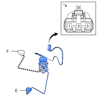
(a) Check that the float moves smoothly between F and E.
(b) Check the fuel sender gauge assembly voltage.
| (1) Apply 5 V between terminals 2 and 3. NOTICE:
HINT: If a stable power supply is not available, connect 4 nickel-metal hydride batteries (1.2 V each) or equivalent in series. |
|
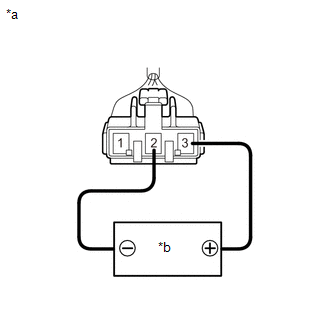
| (2) Measure the voltage according to the value(s) in the table below. Standard Voltage:
*: The output voltage changes depending on the voltage applied to the terminals. Output voltage (F) = (0.851 x Voltage applied to terminals) to (0.921 x Voltage applied to terminals) Output voltage (E) = (0.069 x Voltage applied to terminals) to (0.139 x Voltage applied to terminals) If the result is not as specified, replace the fuel sender gauge assembly. |
|
READ NEXT:
 Installation
INSTALLATION PROCEDURE 1. INSTALL FUEL SENDER GAUGE ASSEMBLY (a) Engage the claw to install the fuel sender gauge assembly to the fuel sub-tank. NOTICE: Be careful not to bend the arm of the fuel send
Precaution
PRECAUTION CAUTION:
Never perform work on fuel system components near any possible ignition sources.
Vaporized fuel could ignite, resulting in a serious accident.
Do not perform work on fuel s
SEE MORE:
Green Indicator Remains Off
DESCRIPTION After power switch on (IG), the DCM (telematics transceiver) will enter into self check mode. The manual (SOS) switch red indicator will illuminate for 2 seconds and turn off followed by the manual (SOS) switch green indicator illuminating and remaining on under normal operation. If neit
Brake Pressure Control Solenoid "D" Control Circuit Short to Battery (C14FA12,...,C14FA49)
DESCRIPTION The ABS solenoid relay and reservoir cut solenoid valves are built into the brake actuator assembly. When the brakes are operating, the reservoir cut solenoid valves supply brake fluid from the brake master cylinder reservoir assembly to the pump motor as necessary. When this DTC is stor
