Lexus ES: Removal
REMOVAL
CAUTION / NOTICE / HINT
The necessary procedures (adjustment, calibration, initialization or registration) that must be performed after parts are removed and installed, or replaced during direct fuel injector assembly removal/installation are shown below.
Necessary Procedures After Parts Removed/Installed/Replaced| Replaced Part or Performed Procedure | Necessary Procedure | Effect/Inoperative Function when Necessary Procedure not Performed | Link |
|---|---|---|---|
|
*: When performing learning using the Techstream.
Click here | |||
| Battery terminal is disconnected/reconnected | Perform steering sensor zero point calibration | Lane Control System (for Gasoline Model) | |
| Pre-collision System (for Gasoline Model) | |||
| Parking Support Brake System (for Gasoline Model)* | |||
| Lighting System (for Gasoline Model) | |||
| Memorize steering angle neutral point | Parking Assist Monitor System (for Gasoline Model) | | |
| Panoramic View Monitor System (for Gasoline Model) | | ||
| Initialize power trunk lid system | Power Trunk Lid System (for Gasoline Model) | | |
| Inspection after repair |
| |
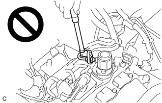
CAUTION:
-
Never perform work on fuel system components near any possible ignition sources.
.png)
- Vaporized fuel could ignite, resulting in a serious accident.
-
Do not perform work on fuel system components without first disconnecting the cable from the negative (-) battery terminal.
.png)
- Sparks could cause vaporized fuel to ignite, resulting in a serious accident.
-
To prevent serious injury due to fuel spray from the high-pressure fuel lines, always discharge fuel system pressure before removing any fuel system components.
NOTICE:
- After the engine switch is turned off, the radio receiver assembly records various types of memory and settings. As a result, after turning the engine switch off, make sure to wait at least 85 seconds before disconnecting the cable from the negative (-) battery terminal. (for Audio and Visual System)
- After the engine switch is turned off, the radio receiver assembly records various types of memory and settings. As a result, after turning the engine switch off, make sure to wait at least 85 seconds before disconnecting the cable from the negative (-) battery terminal. (for Navigation System)
PROCEDURE
1. REMOVE FUEL PUMP ASSEMBLY (for High Pressure)
Click here .gif)
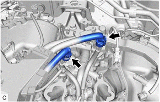
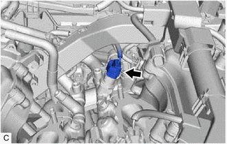
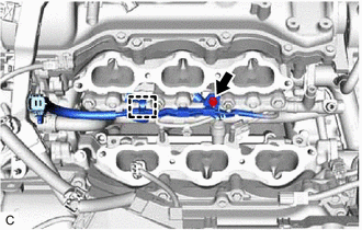
2. REMOVE NO. 2 FUEL PIPE SUB-ASSEMBLY
CAUTION:
To prevent serious injury due to fuel spray from the high-pressure fuel lines, always discharge fuel system pressure before removing any fuel system components.
| (a) Using a 17 mm union nut wrench, loosen the 2 union nuts of the No. 2 fuel pipe sub-assembly. |
|
(b) Remove the No. 2 fuel pipe sub-assembly from the fuel delivery pipe with sensor assembly LH and fuel delivery pipe RH.
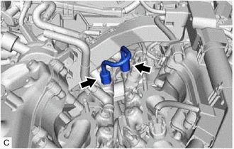
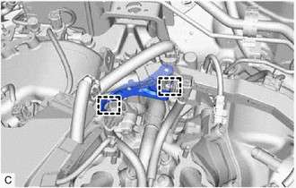
3. REMOVE WIRE HARNESS CLAMP BRACKET
| (a) Disconnect the No. 6 engine wire connector and No. 7 engine wire connector. |
|
| (b) Disengage the 2 clamps to remove the wire harness clamp bracket. |
|
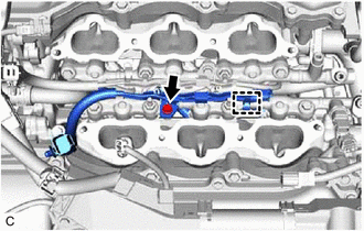
4. REMOVE FUEL DELIVERY PIPE WITH SENSOR ASSEMBLY LH
| (a) Disconnect the fuel pressure sensor connector. |
|
| (b) Remove the bolt. |
|
(c) Disengage the clamp to disconnect the No. 7 engine wire from the fuel delivery pipe with sensor assembly LH.
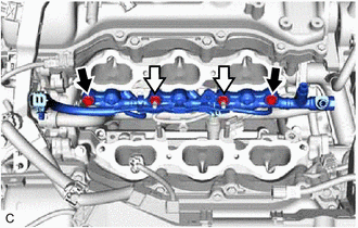
(d) Remove the 2 bolts, 2 nuts and fuel delivery pipe with sensor assembly LH with the 3 direct fuel injector assemblies from the cylinder head LH.
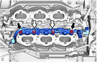
.png) | Bolt |
.png) | Nut |
NOTICE:
- Make sure not to touch or strike the tips of the direct fuel injector assemblies.
- Pull and remove the fuel delivery pipe with sensor assembly LH in a straight line without tilting it.
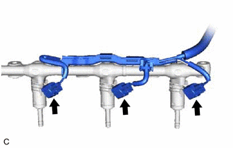
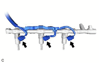
| (e) Disconnect the 3 direct fuel injector assembly connectors. |
|
5. REMOVE FUEL DELIVERY PIPE RH
| (a) Remove the bolt. |
|
(b) Disengage the clamp to disconnect the No. 6 engine wire from the fuel delivery pipe RH.
(c) Remove the 2 bolts, 2 nuts and fuel delivery pipe RH with the 3 direct fuel injector assemblies from the cylinder head sub-assembly.
| | Bolt |
| | Nut |
NOTICE:
- Make sure not to touch or strike the tips of the direct fuel injector assemblies.
- Pull and remove the fuel delivery pipe RH in a straight line without tilting it.
| (d) Disconnect the 3 direct fuel injector assembly connectors. |
|
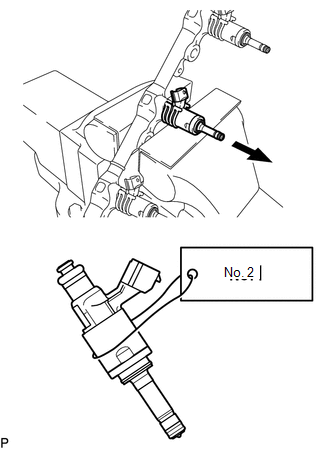
6. REMOVE DIRECT FUEL INJECTOR ASSEMBLY
| (a) Secure the fuel delivery pipe with sensor assembly LH and fuel delivery pipe RH in a vise between aluminum plates and pull out the 6 direct fuel injector assemblies. NOTICE:
|
|
(b) Remove the nozzle holder clamp from each direct fuel injector assembly.
(c) Using needle nose pliers, remove the No. 3 fuel injector back-up ring from each direct fuel injector assembly.
NOTICE:
Do not damage the area that contacts the O-ring.
(d) Remove the O-ring and No. 1 fuel injector back-up ring from each direct fuel injector assembly.
(e) Remove the C-ring and injector vibration insulator from each direct fuel injector assembly.
7. REMOVE FUEL INJECTOR SEAL
| (a) Using the tip of needle nose pliers, pinch and pull the fuel injector seal at several points to stretch it. NOTICE:
|
|
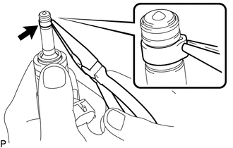
(b) Remove the fuel injector seal from each direct fuel injector assembly.
READ NEXT:
 Inspection
INSPECTION PROCEDURE 1. INSPECT DIRECT FUEL INJECTOR ASSEMBLY NOTICE: This inspection is for checking the direct fuel injector assembly for an open or short. Because the direct fuel injector assembly
Installation
INSTALLATION PROCEDURE 1. INSTALL FUEL INJECTOR SEAL (a) Apply engine conditioner to the area shown in the illustration. Using a piece of cloth, clean carbon deposits from the direct fuel injector
SEE MORE:
Terminals Of Ecu
TERMINALS OF ECU CHECK OUTER MIRROR CONTROL ECU ASSEMBLY (DRIVER DOOR) (a) Disconnect the J28 outer mirror control ECU assembly (driver door) connector. (b) Measure the voltage and resistance according to the value(s) in the table below. HINT: Measure the values on the wire harness side with the co
Installation
INSTALLATION CAUTION / NOTICE / HINT NOTICE: This procedure includes the installation of small-head bolts. Refer to Small-Head Bolts of Basic Repair Hint to identify the small-head bolts. Click here PROCEDURE 1. INSTALL KNOCK CONTROL SENSOR HINT: Perform "Inspection After Repair" after replacing t
