Lexus ES: Parts Location
PARTS LOCATION
ILLUSTRATION
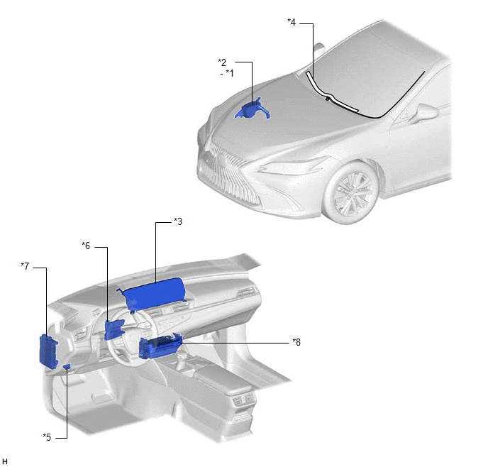
| *1 | DEICER RELAY | *2 | NO. 2 ENGINE ROOM RELAY BLOCK AND NO. 2 ENGINE ROOM JUNCTION BLOCK ASSEMBLY - DEICER FUSE |
| *3 | MULTI-DISPLAY ASSEMBLY - FRONT WIPER DEICER SWITCH | *4 | WINDSHIELD DEICER WIRE (WINDSHIELD GLASS) |
| *5 | DLC3 | *6 | AIR CONDITIONING AMPLIFIER ASSEMBLY |
| *7 | INSTRUMENT PANEL JUNCTION BLOCKASSEMBLY - ECU-IG2 NO. 3 FUSE | *8 | RADIO RECEIVER ASSEMBLY |
READ NEXT:
 System Diagram
SYSTEM DIAGRAM Sender Receiver Signal Communication Method Radio Receiver Assembly Air Conditioning Amplifier Assembly Front wiper deicer switch signal CAN
System Description
SYSTEM DESCRIPTION GENERAL The windshield deicer system uses thin heater wires attached to the inside of the windshield glass to help deice the window surface more quickly. An indicator light illumina
How To Proceed With Troubleshooting
CAUTION / NOTICE / HINT HINT:
Use the following procedure to troubleshoot the windshield deicer system.
*: Use the Techstream.
PROCEDURE 1. VEHICLE BROUGHT TO WORKSHOP
NEXT
SEE MORE:
Windshield Deicer does not Operate
DESCRIPTION When the front wiper deicer switch is operated, the operation signal is transmitted to the air conditioning amplifier assembly directly. When the air conditioning amplifier assembly receives the signal, it turns on the DEICER relay to operate the windshield deicer system. WIRING DIAGRAM
Installation
INSTALLATION PROCEDURE 1. INSTALL BRAKE PEDAL PAD (a) Install the brake pedal pad to the brake pedal support assembly. HINT: Installation is easier after applying a small amount of soapy water. 2. INSTALL STOP LIGHT SWITCH MOUNTING ADJUSTER (a) Engage the 2 claws to install the stop light switch mou
© 2016-2026 Copyright www.lexguide.net
