
Lexus ES: Removal
REMOVAL
CAUTION / NOTICE / HINT
The necessary procedures (adjustment, calibration, initialization, or registration) that must be performed after parts are removed and installed, or replaced during throttle body with motor assembly removal/installation are shown below.
Necessary Procedures After Parts Removed/Installed/Replaced| Replaced Part or Performed Procedure | Necessary Procedure | Effect/Inoperative Function when Necessary Procedure not Performed | Link |
|---|---|---|---|
| Inspection after repair |
| |
PROCEDURE
1. DRAIN ENGINE COOLANT
Click here .gif)
2. REMOVE AIR CLEANER CAP WITH AIR CLEANER HOSE
| (a) Disconnect the mass air flow meter sub-assembly connector. |
|
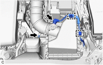
(b) Disengage the 2 wire harness clamps.
(c) Disconnect the vacuum hose from the air cleaner hose.
| (d) Disengage the 2 clamps to disconnect the No. 1 fuel vapor feed hose from the air cleaner hose. |
|
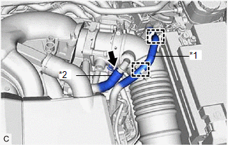
(e) Slide the clip and disconnect the No. 2 ventilation hose from the air cleaner hose.
| (f) Disengage the 2 air cleaner cap clamps. |
|
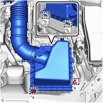
(g) Disengage the 2 guides to separate the air cleaner cap sub-assembly from the air cleaner case sub-assembly.
| (h) Loosen the hose clamp and remove the air cleaner cap with air cleaner hose from the throttle body with motor assembly. |
|
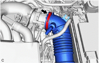
3. REMOVE THROTTLE BODY WITH MOTOR ASSEMBLY
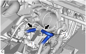
| (a) Slide the 2 clips and disconnect the No. 2 water by-pass hose and No. 3 water by-pass hose from the throttle body with motor assembly. |
|
| (b) Disconnect the throttle body with motor assembly connector. |
|
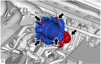
(c) Remove the 4 bolts and throttle body with motor assembly from the intake air surge tank assembly.
NOTICE:
If the throttle body with motor assembly has been struck or dropped, replace it.
4. REMOVE THROTTLE BODY GASKET
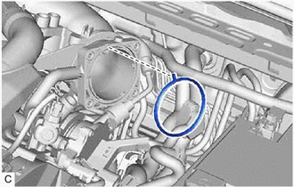
| (a) Remove the throttle body gasket from the intake air surge tank assembly. |
|
READ NEXT:
 Inspection
INSPECTION PROCEDURE 1. INSPECT THROTTLE BODY WITH MOTOR ASSEMBLY (a) Measure the resistance according to the value(s) in the table below. Standard Resistance: Tester Connection Condition S
Installation
INSTALLATION PROCEDURE 1. INSTALL THROTTLE BODY GASKET (a) Install a new throttle body gasket to the intake air surge tank assembly with the protrusion of the throttle body gasket oriented as shown
SEE MORE:
Initialization
INITIALIZATION INITIALIZE POWER WINDOW CONTROL SYSTEM (ALL DOORS) NOTICE:
When any of the door window regulator sub-assemblies, power window regulator motor assemblies, door glass or door glass runs have been removed and reinstalled, the power window control system must be initialized. Functions
On-vehicle Inspection
ON-VEHICLE INSPECTION CAUTION / NOTICE / HINT CAUTION:
To prevent burns, do not touch the engine, exhaust manifold or other high temperature components while the engine is hot.
To prevent burns, do not remove the oil pressure and temperature sensor while the engine is hot. PROCEDURE 1. INS
