Lexus ES: Installation
INSTALLATION
PROCEDURE
1. INSTALL NO. 2 ECM BRACKET
(a) Install the No. 2 ECM bracket to the ECM with the 2 screws.
Torque:
4.5 N·m {46 kgf·cm, 40 in·lbf}
2. INSTALL NO. 1 ECM BRACKET
(a) Install the No. 1 ECM bracket to the ECM with the 2 screws.
Torque:
4.5 N·m {46 kgf·cm, 40 in·lbf}
3. INSTALL ECM
(a) Install the ECM with the 2 bolts and nut.
Torque:
8.0 N·m {82 kgf·cm, 71 in·lbf}
NOTICE:
If the ECM has been struck or dropped, replace it.
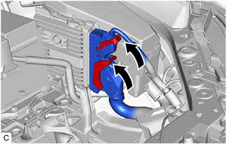
| (b) Connect the 2 ECM connectors and rotate the 2 levers to lock them. NOTICE:
|
|
4. INSTALL AIR CLEANER ASSEMBLY WITH AIR CLEANER HOSE
Click here .gif)
5. INSTALL INLET AIR CLEANER ASSEMBLY
Click here
6. INSTALL COOL AIR INTAKE DUCT SEAL
Click here
7. CONNECT CABLE TO NEGATIVE BATTERY TERMINAL
Click here
8. PERFORM INITIALIZATION
Click here
READ NEXT:
 Components
COMPONENTS ILLUSTRATION *1 AIR CLEANER CAP WITH AIR CLEANER HOSE *2 ENGINE COOLANT TEMPERATURE SENSOR *3 VACUUM HOSE *4 NO. 1 FUEL VAPOR FEED HOSE *5 NO. 2 VENTILATION HOSE
Removal
REMOVAL CAUTION / NOTICE / HINT The necessary procedures (adjustment, calibration, initialization or registration) that must be performed after parts are removed and installed, or replaced during engi
SEE MORE:
Extension Module Malfunction 2 (B1556)
DESCRIPTION This DTC is stored when a malfunction occurs in the Navigation ECU. DTC No. Detection Item DTC Detection Condition Trouble Area B1556 Extension Module Malfunction 2 When any of the following conditions is met:
Internal power supply malfunction
Internal hard drive ma
System Voltage (BATT) Circuit Short to Ground or Open (P056014)
DESCRIPTION Auxiliary battery power is supplied to the BATT terminal of the hybrid vehicle control ECU in order to store DTCs and freeze frame data. Even if the power switch is turned off, back-up power is supplied. DTC No. Detection Item DTC Detection Condition Trouble Area MIL Warning
