Lexus ES: Removal
REMOVAL
CAUTION / NOTICE / HINT
The necessary procedures (adjustment, calibration, initialization or registration) that must be performed after parts are removed and installed, or replaced during rear engine mounting insulator removal/installation are shown below.
Necessary Procedures After Parts Removed/Installed/Replaced| Replaced Part or Performed Procedure | Necessary Procedure | Effect/Inoperative Function when Necessary Procedure not Performed | Link |
|---|---|---|---|
| Battery terminal is disconnected/reconnected | Perform steering sensor zero point calibration | Lane Control System | |
| Pre-collision System | |||
| Parking Support Brake System*1 | |||
| Lighting System | |||
| Memorize steering angle neutral point | Parking Assist Monitor System | | |
| Panoramic View Monitor System | | ||
| Initialize power trunk lid system | Power Trunk Lid System | | |
| Replacement of ECM | Vehicle Identification Number (VIN) registration | MIL comes on | |
| ECU communication ID registration (Immobiliser system) | Engine start function | | |
| Gas leak from exhaust system is repaired | Inspection after repair |
| |
| Replacement of ECM (If transaxle compensation code read from ECM) |
|
| for Initialization: for Registration: |
| Replacement of ECM (If transaxle compensation code not read from ECM) |
| ||
| Replacement of ECM | Code registration (Smart access system with push-button start (for Start Function, Gasoline Model) |
| |
| Replacement of automatic transaxle fluid | ATF thermal degradation estimate reset | The value of the Data List item "ATF Thermal Degradation Estimate" is not estimated correctly | |
| Suspension, tires, etc. (The vehicle height changes because of suspension or tire replacement) | Rear television camera assembly optical axis adjustment (Back camera position setting) | Parking assist monitor system | for Initialization: for Calibration: |
| Perform headlight ECU sub-assembly LH initialization | Lighting system | | |
| Front wheel alignment adjustment |
|
| |
| Front television camera view adjustment | Panoramic View Monitor System | for Initialization for Calibration |
| Replacement of front bumper assembly |
|
| |
-
*1: When performing learning using the Techstream.
Click here
.gif)
- *2: Not necessary when ECM replaced with new one
NOTICE:
- After the engine switch is turned off, the radio receiver assembly records various types of memory and settings. As a result, after turning the engine switch off, make sure to wait at least 85 seconds before disconnecting the cable from the negative (-) battery terminal. (for Audio and Visual System)
- After the engine switch is turned off, the radio receiver assembly records various types of memory and settings. As a result, after turning the engine switch off, make sure to wait at least 85 seconds before disconnecting the cable from the negative (-) battery terminal. (for Navigation System)
PROCEDURE
1. REMOVE FRONT FRAME ASSEMBLY
Click here
2. REMOVE REAR ENGINE MOUNTING INSULATOR
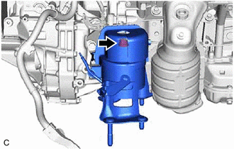
| (a) Remove the bolt and rear engine mounting insulator from the rear engine mounting bracket. |
|
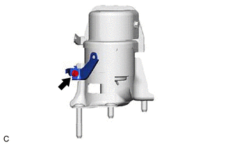
| (b) Remove the bolt and wire harness clamp bracket from the rear engine mounting insulator. |
|
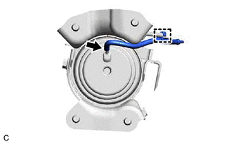
| (c) Disengage the clamp and remove the vacuum hose from the rear engine mounting insulator. |
|
READ NEXT:
 Installation
INSTALLATION PROCEDURE 1. INSTALL REAR ENGINE MOUNTING INSULATOR (a) Engage the clamp and install the vacuum hose to the rear engine mounting insulator. (b) Install the wire harness clamp bracket to t
Components
COMPONENTS ILLUSTRATION *1 V-BANK COVER SUB-ASSEMBLY *2 AIR FUEL RATIO SENSOR (for Bank 1) *3 AIR FUEL RATIO SENSOR (for Bank 2) - - N*m (kgf*cm, ft.*lbf): Specified torque
SEE MORE:
Precaution
PRECAUTION PRECAUTION FOR DISCONNECTING CABLE FROM NEGATIVE BATTERY TERMINAL NOTICE: When disconnecting the cable from the negative (-) battery terminal, initialize the following systems after the cable is reconnected. System Name See Procedure Lane Control System (for Gasoline Model)
Components
COMPONENTS ILLUSTRATION *1 FRONT WHEEL OPENING EXTENSION PAD LH *2 FRONT WHEEL OPENING EXTENSION PAD RH *3 NO. 1 ENGINE UNDER COVER *4 NO. 2 ENGINE UNDER COVER ASSEMBLY N*m (kgf*cm, ft.*lbf): Specified torque - - ILLUSTRATION *1 OIL PRESSURE AND TEMPERATURE SE
