Lexus ES: Removal
REMOVAL
CAUTION / NOTICE / HINT
The necessary procedures (adjustment, calibration, initialization or registration) that must be performed after parts are removed and installed, or replaced during transmission control cable assembly removal/installation are shown below.
Necessary Procedures After Parts Removed/Installed/Replaced| Replaced Part or Performed Procedure | Necessary Procedure | Effect/Inoperative Function when Necessary Procedure not Performed | Link |
|---|---|---|---|
| Battery terminal is disconnected/reconnected | Perform steering sensor zero point calibration | Lane Control System (for Gasoline Model) | |
| Pre-collision System (for Gasoline Model) | |||
| Parking Support Brake System (for Gasoline Model)*1 | |||
| Lighting System (for Gasoline Model) | |||
| Memorize steering angle neutral point | Parking Assist Monitor System (for Gasoline Model) | | |
| Panoramic View Monitor System (for Gasoline Model) | | ||
| Initialize power trunk lid system | Power Trunk Lid System (for Gasoline Model) | | |
| Replacement of ECM | Vehicle Identification Number (VIN) registration | MIL comes on | |
| ECU communication ID registration (Immobiliser system) | Engine start function | | |
| Replacement of ECM (If transaxle compensation code read from ECM) |
|
| for Initialization: for Registration: |
| Replacement of ECM (If transaxle compensation code not read from ECM) |
| ||
| Replacement of ECM | Code registration (Smart access system with push-button start (for Start Function, Gasoline Model) |
| |
| Gas leak from exhaust system is repaired | Inspection after repair |
| |
-
*1: When performing learning using the Techstream.
Click here
.gif)
- *2: Not necessary when ECM replaced with new one.
PROCEDURE
1. REMOVE BATTERY
Click here
2. REMOVE ECM
Click here
3. REMOVE BATTERY CLAMP SUB-ASSEMBLY
Click here
4. REMOVE FRONT EXHAUST PIPE ASSEMBLY
Click here
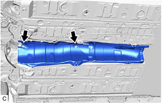
5. REMOVE FRONT LOWER NO. 1 FLOOR HEAT INSULATOR
| (a) Remove the 2 nuts and front lower No. 1 floor heat insulator from the vehicle body. |
|
6. REMOVE TRANSMISSION FLOOR SHIFT ASSEMBLY
Click here
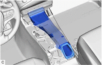
7. REMOVE NO. 1 CONSOLE BOX DUCT
| (a) Remove the No. 1 console box duct. |
|
8. REMOVE TRANSMISSION CONTROL CABLE ASSEMBLY
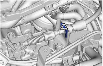
| (a) While disengaging the clip as shown in the illustration, disconnect the transmission control cable assembly from the transmission control shaft lever together with the clip. |
|
.png)
| (b) Remove the clip and disconnect the transmission control cable assembly from the No. 1 transmission control cable bracket. |
|
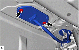
| (c) Remove the 2 nuts and disconnect the transmission control cable assembly from the vehicle body. |
|
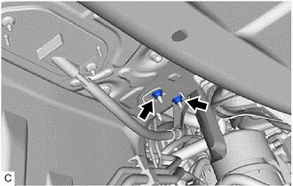
| (d) Remove the 2 nuts and then remove the transmission control cable assembly from the vehicle body. |
|
READ NEXT:
 Components
COMPONENTS ILLUSTRATION *A Type A *B Type B *1 FRONT FENDER APRON SEAL LH *2 FRONT WHEEL OPENING EXTENSION PAD LH *3 FRONT WHEEL OPENING EXTENSION PAD RH *4 NO. 1 ENGINE
Installation
INSTALLATION PROCEDURE 1. INSTALL TRANSMISSION WIRE (a) Coat the O-ring of the transmission wire with Toyota Genuine ATF WS. (b) Install the transmission wire to the automatic transaxle
SEE MORE:
Data List / Active Test
DATA LIST / ACTIVE TEST ACTIVE TEST HINT: Using the Techstream to perform Active Tests allows relays, VSVs, actuators and other items to be operated without removing any parts. This non-intrusive functional inspection can be very useful because intermittent operation may be discovered before parts o
Removal
REMOVAL PROCEDURE 1. SECURE VEHICLE (a) Fully apply the parking brake and chock a wheel. CAUTION:
Make sure to apply the parking brake and chock a wheel before performing this procedure.
If the vehicle is not secure and the shift lever is moved to N, the vehicle may suddenly move, possibly resu
