Lexus ES: Installation
INSTALLATION
PROCEDURE
1. INSTALL TRANSMISSION WIRE
| (a) Coat the O-ring of the transmission wire with Toyota Genuine ATF WS. |
|
.png)
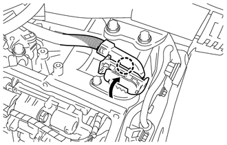
(b) Install the transmission wire to the automatic transaxle case sub-assembly with the bolt.
Torque:
5.4 N·m {55 kgf·cm, 48 in·lbf}
(c) Connect the transmission revolution sensor (NT) connector and transmission revolution sensor (NC) connector.
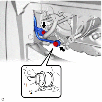
(d) Install the temperature sensor to the transmission valve body assembly with the bolt and temperature sensor clamp.
Torque:
10.8 N·m {110 kgf·cm, 8 ft·lbf}
NOTICE:
To prevent it from being pinched between the transmission valve body assembly and the transmission case side cover, pass the transmission revolution sensor (NC) wire under the transmission wire (temperature sensor wire) as shown in the illustration.
.png)
| *a | Transmission Wire (Temperature Sensor Wire) |
| *b | Transmission Revolution Sensor (NC) Wire |
(e) Connect the 9 solenoid valve connectors.
.png)
.png) | Do not let transmission wire protrude into this area. |
- To prevent it from being pinched between the transmission valve body assembly and the transmission case side cover, do not let the transmission wire ride up over the area shown in the illustration.
- To prevent it from being pinched between the transmission case side cover and the automatic transaxle case sub-assembly, do not let the transmission wire protrude toward the transmission case side cover installation surface.
.png)
| (f) Engage the clamp to connect the transmission wire to the solenoid lock plate. |
|
.png)
| (g) Connect the transmission wire connector, rotate the lever and engage the claw. HINT: Rotate the lever until the claw of the transmission wire connector makes a click sound. |
|
2. INSTALL TRANSMISSION CASE SIDE COVER (for TMC, TMMWV Made)
HINT:
-
TMC (TOYOTA) Made, AW (AISIN AW) Made and TMMWV (TOYOTA) Made components can be identified by the differing locations where the serial number is stamped.
.png)
*a
TMC Made
*b
AW, TMMWV Made
-
for AW, TMMWV Made:
-
Refer to introduction and check the serial number. Confirm the factory at which the automatic transaxle assembly was manufactured according to the following table.
Serial Number
Factory
##6########
for AW (AISIN AW) Made
##A########
for TMMWV Made
-
Refer to introduction and check the serial number. Confirm the factory at which the automatic transaxle assembly was manufactured according to the following table.
(a) Clean the transmission case side cover installation surface of the automatic transaxle case sub-assembly.
.png)
| | Area to be Cleaned |
NOTICE:
Completely remove any oil or grease from the contact surfaces of the automatic transaxle case sub-assembly.
| (b) Clean the 3 bolt holes shown in the illustration. |
|
.png)
| (c) Apply adhesive to 2 or 3 threads on the end of the bolt (A) and 2 bolts (D). Adhesive: Toyota Genuine Adhesive 1324, Three Bond 1324 or equivalent NOTICE: Make sure to install the bolts immediately after applying adhesive to prevent foreign matter from attaching to them. HINT: The bolt (A) and 2 bolts (D) are in the locations shown in the following step. |
|
.png)
| (d) Temporarily install a new transmission case side cover to the automatic transaxle case sub-assembly with the 2 bolts ((A) and (B)). NOTICE:
|
|
.png)
(e) Temporarily install the 6 bolts (C) and 2 bolts (D).
NOTICE:
Bolt (D) is an adhesive-coated bolt.
| (f) Fully tighten the 10 bolts in the order shown in the illustration. Torque: Bolt (A) and Bolt (D) : 6.5 N·m {66 kgf·cm, 58 in·lbf} Bolt (B) and Bolt (C) : 7.0 N·m {71 kgf·cm, 62 in·lbf} |
|
.png)
3. INSTALL TRANSMISSION CASE SIDE COVER (for AISIN AW Made)
HINT:
-
TMC (TOYOTA) Made, AW (AISIN AW) Made and TMMWV (TOYOTA) Made components can be identified by the differing locations where the serial number is stamped.
*a
TMC Made
*b
AW, TMMWV Made
-
for AW, TMMWV Made:
-
Refer to introduction and check the serial number. Confirm the factory at which the automatic transaxle assembly was manufactured according to the following table.
Serial Number
Factory
##6########
for AW (AISIN AW) Made
##A########
for TMMWV Made
-
Refer to introduction and check the serial number. Confirm the factory at which the automatic transaxle assembly was manufactured according to the following table.
(a) Clean the transmission case side cover installation surface of the automatic transaxle case sub-assembly.
| | Area to be Cleaned |
NOTICE:
Completely remove any oil or grease from the contact surfaces of the automatic transaxle case sub-assembly.
| (b) Temporarily install a new transmission case side cover to the automatic transaxle case sub-assembly with the 2 bolts ((A) and (B)). NOTICE: To avoid damaging the gasket, prevent it from contacting the surrounding area during installation procedures. |
|
.png)
(c) Temporarily install the 8 bolts (C).
| (d) Fully tighten the 10 bolts in the order shown in the illustration. Torque: 7.0 N·m {71 kgf·cm, 62 in·lbf} |
|
.png)
4. INSTALL OIL COOLER UNION SUB-ASSEMBLY
| (a) Pass the oil cooler union sub-assembly through 2 new gaskets and temporarily install it to the automatic transaxle case sub-assembly with the oil cooler union bolt. |
|
(b) Temporarily install the oil cooler union sub-assembly bracket portion to the automatic transaxle case sub-assembly with the bolt.
(c) Fully tighten the oil cooler union bolt.
Torque:
22.6 N·m {230 kgf·cm, 17 ft·lbf}
(d) Fully tighten the bolt.
Torque:
12 N·m {122 kgf·cm, 9 ft·lbf}
5. INSTALL FRONT SUSPENSION MEMBER DYNAMIC DAMPER
Click here .gif)
6. INSTALL FRONT ENGINE MOUNTING INSULATOR
Click here
7. ADJUST AUTOMATIC TRANSAXLE FLUID
Click here
8. INSTALL FRONT FENDER APRON SEAL LH
Click here
9. INSTALL NO. 3 ENGINE UNDER COVER
Click here
10. INSTALL NO. 1 ENGINE UNDER COVER
Click here
11. INSTALL FRONT WHEEL OPENING EXTENSION PAD LH
Click here
12. INSTALL FRONT WHEEL OPENING EXTENSION PAD RH
Click here
13. INSTALL FRONT WHEEL LH
Click here
READ NEXT:
 Removal
REMOVAL CAUTION / NOTICE / HINT The necessary procedures (adjustment, calibration, initialization or registration) that must be performed after parts are removed and installed, or replaced during tran
Components
COMPONENTS ILLUSTRATION *1 TRANSMISSION VALVE BODY ASSEMBLY *2 TRANSAXLE CASE GASKET *3 NO. 1 FRONT OIL PUMP COVER GASKET *4 NO. 2 FRONT OIL PUMP COVER GASKET Tightening tor
SEE MORE:
EV drive mode
In EV drive mode, electric power is
supplied by the hybrid battery
(traction battery), and only the
electric motor (traction motor) is
used to drive the vehicle.
This mode allows you to drive in residential
areas early in the morning
and late at night, or in indoor parking
lots etc. withou
Components
COMPONENTS ILLUSTRATION *1 COURTESY LIGHT ASSEMBLY *2 REAR DOOR TRIM BOARD SUB-ASSEMBLY *3 REAR DOOR UPPER TRIM PAD *4 REAR POWER WINDOW REGULATOR SWITCH ASSEMBLY WITH REAR DOOR UPPER ARMREST BASE PANEL ILLUSTRATION *A w/ Rear Door Sunshade - - *1 CURTAIN HOOK
