Lexus ES: Removal
REMOVAL
CAUTION / NOTICE / HINT
The necessary procedures (adjustment, calibration, initialization or registration) that must be performed after parts are removed and installed, or replaced during transmission oil cooler removal/installation are shown below.
Necessary Procedures After Parts Removed/Installed/Replaced| Replaced Part or Performed Procedure | Necessary Procedure | Effect/Inoperative Function when Necessary Procedure not Performed | Link |
|---|---|---|---|
| Battery terminal is disconnected/reconnected | Perform steering sensor zero point calibration | Lane Control System (for Gasoline Model) | |
| Pre-collision System (for Gasoline Model) | |||
| Parking Support Brake System (for Gasoline Model)*1 | |||
| Lighting System (for Gasoline Model) | |||
| Memorize steering angle neutral point | Parking Assist Monitor System (for Gasoline Model) | | |
| Panoramic View Monitor System (for Gasoline Model) | | ||
| Initialize power trunk lid system | Power Trunk Lid System (for Gasoline Model) | | |
| Replacement of ECM | Vehicle Identification Number (VIN) registration | MIL comes on | |
| ECU communication ID registration (Immobiliser system) | Engine start function | | |
| Replacement of ECM (If transaxle compensation code read from ECM) |
|
| for Initialization: for Registration: |
| Replacement of ECM (If transaxle compensation code not read from ECM) |
| ||
| Replacement of ECM | Code registration (Smart access system with push-button start (for Start Function, Gasoline Model) |
| |
| Replacement of automatic transaxle fluid | ATF thermal degradation estimate reset | The value of the Data List item "ATF Thermal Degradation Estimate" is not estimated correctly | |
-
*1: When performing learning using the Techstream.
Click here
.gif)
- *2: Not necessary when ECM replaced with new one.
PROCEDURE
1. REMOVE BATTERY
Click here
2. REMOVE ECM
Click here
3. REMOVE BATTERY CLAMP SUB-ASSEMBLY
Click here
4. REMOVE FRONT WHEEL LH
Click here
5. REMOVE FRONT WHEEL OPENING EXTENSION PAD LH
Click here
6. REMOVE FRONT WHEEL OPENING EXTENSION PAD RH
Click here
7. REMOVE NO. 1 ENGINE UNDER COVER
Click here
8. REMOVE NO. 3 ENGINE UNDER COVER
Click here
9. REMOVE FRONT FENDER APRON SEAL LH
Click here
10. DRAIN ENGINE COOLANT
Click here
11. DRAIN AUTOMATIC TRANSAXLE FLUID
Click here
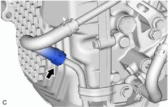
12. DISCONNECT OUTLET NO. 1 OIL COOLER HOSE
| (a) Slide the clip and disconnect the outlet No. 1 oil cooler hose from the oil cooler union sub-assembly. HINT: Use a container to catch any automatic transaxle fluid which flows out of the outlet No. 1 oil cooler hose and oil cooler union sub-assembly. |
|
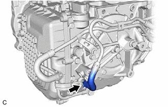
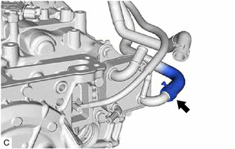
13. DISCONNECT INLET NO. 1 OIL COOLER HOSE
| (a) Slide the clip and disconnect the inlet No. 1 oil cooler hose from the No. 1 oil cooler outlet tube sub-assembly. HINT: Use a container to catch any automatic transaxle fluid which flows out of the inlet No. 1 oil cooler hose and No. 1 oil cooler outlet tube sub-assembly. |
|
14. REMOVE NO. 1 OIL COOLER TUBE SUB-ASSEMBLY WITHOUT HOSE
| (a) Remove the 2 bolts to disconnect the No. 1 oil cooler tube sub-assembly without hose from the automatic transaxle case sub-assembly. |
|
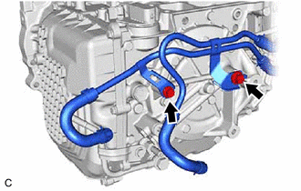
| (b) Slide the clip and disconnect the inlet No. 2 oil cooler hose from the transmission oil cooler. HINT: Use a container to catch any automatic transaxle fluid which flows out of the inlet No. 2 oil cooler hose and transmission oil cooler. |
|
| (c) Slide the clip and disconnect the outlet No. 2 oil cooler hose to remove the No. 1 oil cooler tube sub-assembly without hose from the transmission oil cooler. HINT: Use a container to catch any automatic transaxle fluid which flows out of the outlet No. 2 oil cooler hose and transmission oil cooler. |
|
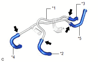
| (d) Slide the 4 clips and remove the inlet No. 1 oil cooler hose, inlet No. 2 oil cooler hose, outlet No. 1 oil cooler hose and outlet No. 2 oil cooler hose from the No. 1 oil cooler tube sub-assembly without hose. |
|
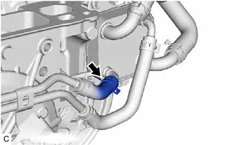
15. DISCONNECT NO. 1 WATER BY-PASS HOSE
| (a) Disengage the 3 clamps to remove the transmission breather clamp. |
|
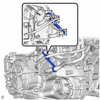
| (b) Slide the clip and disconnect the No. 1 water by-pass hose from the transmission oil cooler. HINT: Use a container to catch any coolant which flows out of the No. 1 water by-pass hose and transmission oil cooler. |
|
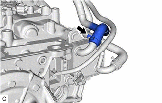
16. DISCONNECT WATER BY-PASS HOSE ASSEMBLY
| (a) Slide the clip and disconnect the water by-pass hose assembly from the transmission oil cooler. HINT: Use a container to catch any coolant which flows out of the water by-pass hose assembly and transmission oil cooler. |
|
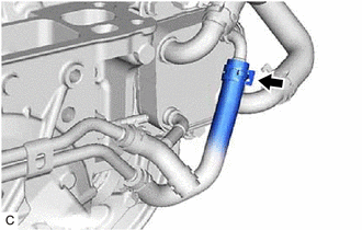
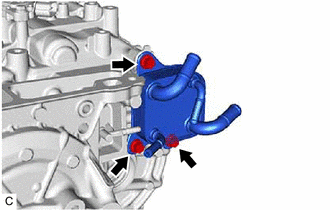
17. REMOVE TRANSMISSION OIL COOLER
| (a) Remove the 3 bolts and transmission oil cooler from the automatic transaxle case sub-assembly. HINT: Use a container to catch any coolant and automatic transaxle fluid which flow out of the transmission oil cooler. |
|
READ NEXT:
 Components
COMPONENTS ILLUSTRATION *1 CLUTCH DRUM OIL SEAL RING *2 FRONT OIL PUMP BODY *3 FRONT OIL PUMP DRIVE GEAR *4 FRONT OIL PUMP DRIVEN GEAR *5 OIL STRAINER ASSEMBLY *6 RING PI
Disassembly
DISASSEMBLY PROCEDURE 1. REMOVE CLUTCH DRUM OIL SEAL RING (a) Remove the 4 clutch drum oil seal rings from the stator shaft assembly. 2. REMOVE OIL STRAINER ASSEMBLY (a) Using a T30
SEE MORE:
Diagnosis System
DIAGNOSIS SYSTEM DESCRIPTION (a) The hybrid vehicle control ECU has a self-diagnosis system. If the computer, hybrid control system, or a component is not working properly, the ECU records the conditions that relate to the fault. The ECU also illuminates the master warning light in the combination m
Diagnostic Trouble Code Chart
DIAGNOSTIC TROUBLE CODE CHART Front Radar Sensor System DTC No. Detection Item Link C1A1100 Front Radar Sensor Optical Axis Misalignment Malfunction C1A8C46 Main Microcomputer in Front Radar Sensor Calibration/Parameter Memory Failure C1A8D1C Power Supply Circuit i
