Lexus ES: Components
COMPONENTS
ILLUSTRATION
.png)
| *A | for Gasoline Model 2WD | *B | for RH Side |
| *C | for LH Side | - | - |
| *1 | NO. 1 FLOOR UNDER COVER | *2 | NO. 2 FLOOR UNDER COVER |
.png) | N*m (kgf*cm, ft.*lbf): Specified torque | - | - |
ILLUSTRATION
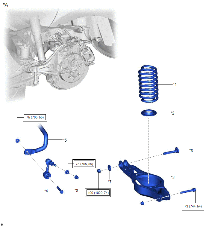
| *A | for 2WD | - | - |
| *1 | REAR COIL SPRING | *2 | REAR LOWER COIL SPRING INSULATOR |
| *3 | REAR NO. 2 SUSPENSION ARM ASSEMBLY | *4 | REAR STABILIZER LINK ASSEMBLY |
| *5 | REAR STABILIZER BAR | *6 | REAR SUSPENSION TOE ADJUST CAM SUB-ASSEMBLY |
| *7 | NO. 2 CAMBER ADJUST CAM | *8 | CAP |
.png) | Tightening torque for "Major areas involving basic vehicle performance such as moving/turning/stopping": N*m (kgf*cm, ft.*lbf) | - | - |
ILLUSTRATION
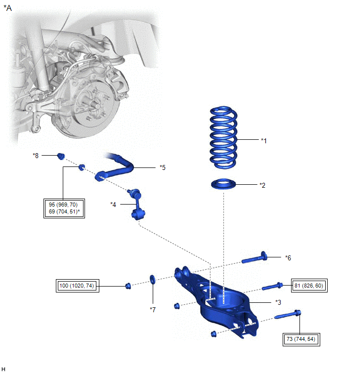
| *A | for AWD | - | - |
| *1 | REAR COIL SPRING | *2 | REAR LOWER COIL SPRING INSULATOR |
| *3 | REAR NO. 2 SUSPENSION ARM ASSEMBLY | *4 | REAR STABILIZER LINK ASSEMBLY |
| *5 | REAR STABILIZER BAR | *6 | REAR SUSPENSION TOE ADJUST CAM SUB-ASSEMBLY |
| *7 | NO. 2 CAMBER ADJUST CAM | *8 | CAP |
| | Tightening torque for "Major areas involving basic vehicle performance such as moving/turning/stopping": N*m (kgf*cm, ft.*lbf) | - | - |
ILLUSTRATION
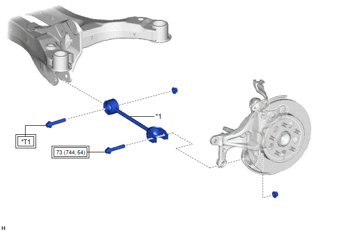
| *1 | REAR NO. 1 SUSPENSION ARM ASSEMBLY | - | - |
| | Tightening torque for "Major areas involving basic vehicle performance such as moving/turning/stopping": N*m (kgf*cm, ft.*lbf) | *T1 | for 2WD: 73 N*m (744 kgf*cm, 54 ft.*lbf) for AWD: 115 N*m (1173 kgf*cm, 85 ft.*lbf) |
READ NEXT:
 Removal
REMOVAL CAUTION / NOTICE / HINT The necessary procedures (adjustment, calibration, initialization, or registration) that must be performed after parts are removed and installed, or replaced during rea
Removal
REMOVAL CAUTION / NOTICE / HINT The necessary procedures (adjustment, calibration, initialization, or registration) that must be performed after parts are removed and installed, or replaced during rea
Installation
INSTALLATION CAUTION / NOTICE / HINT HINT:
Use the same procedure for the RH side and LH side.
The following procedure is for the LH side.
PROCEDURE 1. TEMPORARILY INSTALL REAR NO. 1 SUSPENSIO
SEE MORE:
Tilt and Telescopic Manual Switch Circuit
DESCRIPTION Different voltage values are sent to the multiplex tilt and telescopic ECU by operating the tilt and telescopic switch. The multiplex tilt and telescopic ECU then judges which motor and in which direction that motor should operate based on the voltage value. WIRING DIAGRAM PROCEDURE
Data List / Active Test
DATA LIST / ACTIVE TEST ACTIVE TEST HINT: Using the Techstream to perform Active Tests allows relays, VSVs, actuators and other items to be operated without removing any parts. This non-intrusive functional inspection can be very useful because intermittent operation may be discovered before parts o
