Lexus ES: Removal
REMOVAL
PROCEDURE
1. SECURE VEHICLE
(a) Fully apply the parking brake and chock a wheel.
CAUTION:
- Make sure to apply the parking brake and chock a wheel before performing this procedure.
- If the vehicle is not secure and the shift lever is moved to N, the vehicle may suddenly move, possibly resulting in an accident or serious injury.
.png)
2. REMOVE SHIFT LOCK RELEASE BUTTON COVER
| (a) Apply protective tape to the upper console panel sub-assembly at the location shown in the illustration. |
|
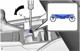
(b) Using a screwdriver with its tip wrapped with protective tape, disengage the 2 claws and guide to remove the shift lock release button cover from the upper console panel sub-assembly.
NOTICE:
Be careful not to damage the shift lock release button cover and upper console panel sub-assembly.
3. REMOVE SHIFT LEVER KNOB SUB-ASSEMBLY
Click here .gif)
4. REMOVE CONSOLE BOX ASSEMBLY
Click here
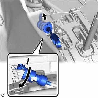
5. DISCONNECT TRANSMISSION CONTROL CABLE ASSEMBLY
NOTICE:
Before disconnecting the transmission control cable assembly, check that the shift lever is in N.
| (a) Disconnect the transmission control cable assembly from the transmission floor shift assembly. |
|

| (b) Rotate the lock nut counterclockwise approximately 180° and, while holding the lock nut in that position, disconnect the transmission control cable assembly from the transmission floor shift assembly. |
|
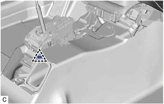
6. REMOVE TRANSMISSION FLOOR SHIFT ASSEMBLY
| (a) Remove the 4 bolts. |
|
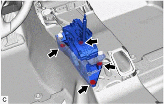
| (b) Remove the clip to disconnect the No. 1 console box duct from the transmission floor shift assembly. |
|
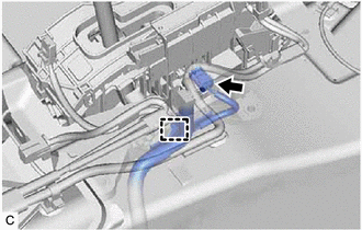
| (c) Disconnect the transmission control switch connector. |
|
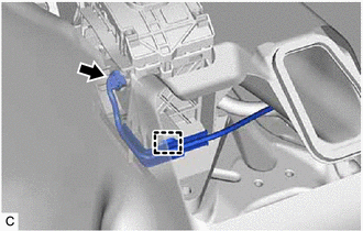
(d) Disengage the clamp to disconnect the wire harness from the transmission floor shift assembly.
| (e) Disconnect the shift lock control ECU connector. |
|
(f) Disengage the clamp to disconnect the wire harness from the transmission floor shift assembly.
(g) Remove the transmission floor shift assembly.
READ NEXT:
 Components
COMPONENTS ILLUSTRATION *1 NO. 1 SWITCH WIRE *2 SHIFT PADDLE SWITCH (TRANSMISSION SHIFT SWITCH ASSEMBLY) *3 STEERING PAD SWITCH ASSEMBLY *4 STEERING WHEEL ASSEMBLY *5 SHIFT P
Inspection
INSPECTION PROCEDURE 1. INSPECT SHIFT PADDLE SWITCH (TRANSMISSION SHIFT SWITCH ASSEMBLY) (a) Shift Paddle Switch LH (Transmission Shift Switch Assembly): (1) Measure the resistance according to the
SEE MORE:
Installation
INSTALLATION CAUTION / NOTICE / HINT NOTICE: This procedure includes the installation of small-head bolts. Refer to Small-Head Bolts of Basic Repair Hint to identify the small-head bolts. Click here PROCEDURE 1. INSTALL NO. 2 FUEL PRESSURE SENSOR HINT: Perform "Inspection After Repair" after repla
Certification ECU Vehicle Information Reading/Writing Process Malfunction (B15F7)
DESCRIPTION This DTC is stored when items controlled by the certification ECU (smart key ECU assembly) cannot be customized via the navigation system vehicle customization screen. HINT: The certification ECU (smart key ECU assembly) controls the smart access system with push-button start (for Entry
