Lexus ES: Components
COMPONENTS
ILLUSTRATION
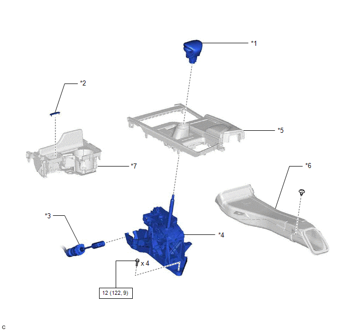
| *1 | SHIFT LEVER KNOB SUB-ASSEMBLY | *2 | SHIFT LOCK RELEASE BUTTON COVER |
| *3 | TRANSMISSION CONTROL CABLE ASSEMBLY | *4 | TRANSMISSION FLOOR SHIFT ASSEMBLY |
| *5 | REAR UPPER CONSOLE PANEL SUB-ASSEMBLY | *6 | NO. 1 CONSOLE BOX DUCT |
| *7 | UPPER CONSOLE PANEL SUB-ASSEMBLY | - | - |
.png) | N*m (kgf*cm, ft.*lbf): Specified torque | - | - |
ILLUSTRATION
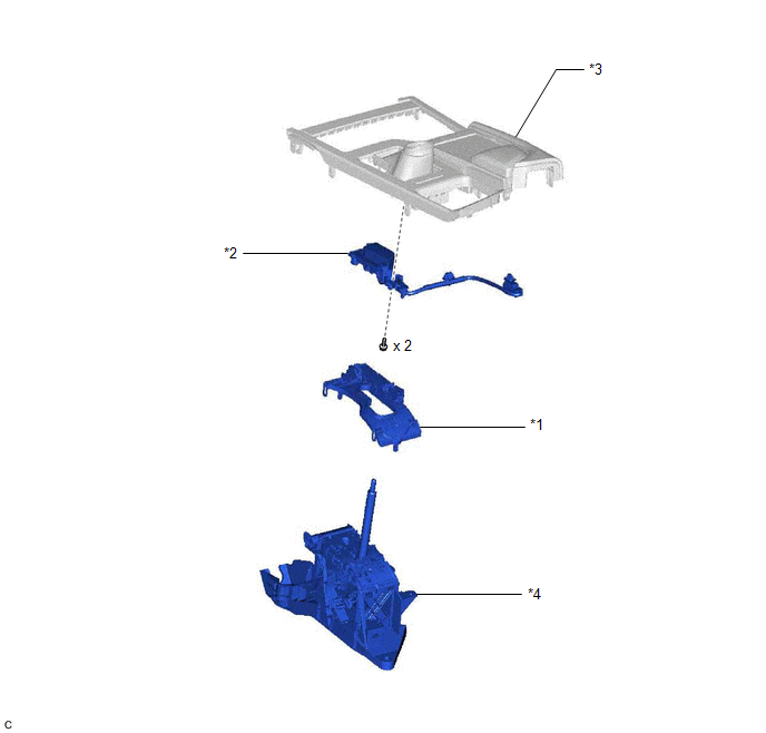
| *1 | LOWER POSITION INDICATOR HOUSING | *2 | SHIFT POSITION INDICATOR |
| *3 | REAR UPPER CONSOLE PANEL SUB-ASSEMBLY | *4 | SHIFT LOCK CONTROL UNIT ASSEMBLY |
READ NEXT:
 Disassembly
DISASSEMBLY PROCEDURE 1. REMOVE SHIFT POSITION INDICATOR (a) Disengage the 2 clamps to disconnect the wire harness. (b) Remove the 2 screws. (c) Disengage the claw and
Inspection
INSPECTION PROCEDURE 1. INSPECT SHIFT LOCK CONTROL ECU HINT: If the results of the following inspections are as specified but a malfunction has occurred, replace the shift lock control unit assembly.
Installation
INSTALLATION PROCEDURE 1. INSTALL TRANSMISSION FLOOR SHIFT ASSEMBLY (a) Engage the clamp to connect the wire harness to the transmission floor shift assembly. (b) Connect the shift lock control ECU co
SEE MORE:
Removal
REMOVAL CAUTION / NOTICE / HINT The necessary procedures (adjustment, calibration, initialization, or registration) that must be performed after parts are removed and installed, or replaced during rear television camera assembly removal/installation are shown below. Necessary Procedure After Parts R
Diagnostic Trouble Code Chart
DIAGNOSTIC TROUBLE CODE CHART Charging System DTC No. Detection Item Warning Indicate Memory Link P058A01 Auxiliary Battery Monitor Module Range/Performance Charge warning is not displayed DTC stored P162B87 Lost Communication with Battery Monitor Module Missing Messa
© 2016-2026 Copyright www.lexguide.net
