Lexus ES: Removal
REMOVAL
CAUTION / NOTICE / HINT
The necessary procedures (adjustment, calibration, initialization, or registration) that must be performed after parts are removed and installed, or replaced during motor cooling cooler removal/installation are shown below.
Necessary Procedure After Parts Removed/Installed/Replaced| Replaced Part or Performed Procedure | Necessary Procedure | Effect/Inoperative Function when Necessary Procedure not Performed | Link |
|---|---|---|---|
| Auxiliary battery terminal is disconnected/reconnected | Perform steering sensor zero point calibration | Lane Control System (for HV Model) | |
| Pre-collision System (for HV Model) | |||
| Parking Support Brake System (for HV Model)* | |||
| Lighting System (for HV Model) | |||
| Memorize steering angle neutral point | Parking Assist Monitor System (for HV Model) | | |
| Panoramic View Monitor System (for HV Model) | | ||
| Initialize power trunk lid system | Power Trunk Lid System (for HV Model) | | |
| Replacement of ECM | Perform Vehicle Identification Number (VIN) registration | MIL illuminates | |
| Replacement of inverter with converter assembly | Resolver learning |
| |
-
*: When performing learning using the Techstream.
Click here
.gif)
CAUTION:
-
Orange wire harnesses and connectors indicate high-voltage circuits. To prevent electric shock, always follow the procedure described in the repair manual.
.png)
Click here
-
To prevent electric shock, wear insulated gloves when working on wire harnesses and components of the high voltage system.
.png)
NOTICE:
- After the engine switch is turned off, the radio receiver assembly records various types of memory and settings. As a result, after turning the engine switch off, make sure to wait at least 85 seconds before disconnecting the cable from the negative (-) battery terminal. (for Audio and Visual System)
- After the engine switch is turned off, the radio receiver assembly records various types of memory and settings. As a result, after turning the engine switch off, make sure to wait at least 85 seconds before disconnecting the cable from the negative (-) battery terminal. (for Navigation System)
PROCEDURE
1. REMOVE FRONT WHEEL OPENING EXTENSION PAD RH
Click here
2. REMOVE FRONT WHEEL OPENING EXTENSION PAD LH
Click here
3. REMOVE NO. 1 ENGINE UNDER COVER
Click here
4. REMOVE NO. 2 ENGINE UNDER COVER ASSEMBLY
Click here
5. REMOVE FRONT FENDER APRON SEAL LH
Click here
6. REMOVE INVERTER WITH CONVERTER ASSEMBLY
Click here
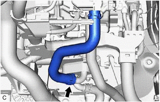
7. REMOVE NO. 1 INVERTER COOLING HOSE
| (a) Slide the clip and remove the No. 1 inverter cooling hose from the motor cooling cooler. |
|
8. DISCONNECT NO. 5 INVERTER COOLING HOSE
Click here
9. REMOVE MOTOR COOLING COOLER
| (a) Remove the oil cooler union bolt and gasket to disconnect the No. 2 motor cooling pipe from the hybrid vehicle transaxle assembly. |
|
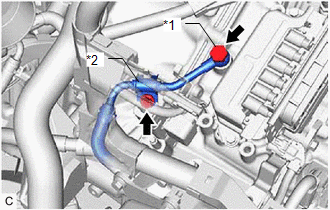
(b) Remove the bolt and No. 1 oil cooler tube clamp to disconnect the No. 2 motor cooling pipe from the hose bracket.
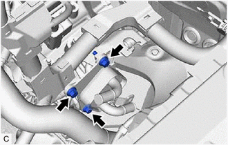
| (c) Remove the 3 bolts to disconnect the motor cooling cooler from the No. 1 transmission control cable bracket. |
|
| (d) Slide the clip and disconnect the No. 1 motor cooling hose from the transaxle housing tube connector. NOTICE: Make sure not to remove the No. 1 motor cooling hose from the motor cooling cooler as the motor cooling cooler may be deformed. |
|
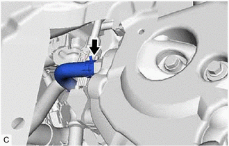
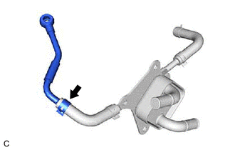
10. REMOVE NO. 2 MOTOR COOLING PIPE
| (a) Slide the clip and remove the No. 2 motor cooling pipe from the No. 2 motor cooling hose. NOTICE: Make sure not to remove the No. 2 motor cooling hose from the motor cooling cooler as the motor cooling cooler may be deformed. |
|
READ NEXT:
 Shift Lever Knob
ComponentsCOMPONENTS ILLUSTRATION *1 SHIFT LEVER KNOB SUB-ASSEMBLY - - InstallationINSTALLATION PROCEDURE 1. INSTALL SHIFT LEVER KNOB SUB-ASSEMBLY (a) Install the shift lever knob su
Adjustment
ADJUSTMENT PROCEDURE 1. SECURE VEHICLE (a) Fully apply the parking brake and chock a wheel. CAUTION:
Make sure to apply the parking brake and chock a wheel before performing this procedure.
If th
SEE MORE:
Brake Warning Light Remains ON
DESCRIPTION The skid control ECU (brake booster with master cylinder assembly) is connected to the combination meter assembly via CAN communication. If any of the following is detected, the brake warning light / red (malfunction) remains on:
The skid control ECU (brake booster with master cylinde
Removal
REMOVAL PROCEDURE 1. REMOVE FRONT WHEEL RH Click here 2. REMOVE FRONT FENDER APRON SEAL RH Click here 3. REMOVE V-BANK COVER SUB-ASSEMBLY Click here 4. REMOVE CAMSHAFT TIMING OIL CONTROL SOLENOID ASSEMBLY (for Exhaust Side of Bank 1) Click here 5. SET NO. 1 CYLINDER TO TDC/COMPRESSION
