Lexus ES: Removal
REMOVAL
CAUTION / NOTICE / HINT
The necessary procedures (adjustment, calibration, initialization, or registration) that must be performed after parts are removed and installed, or replaced during hybrid vehicle transaxle assembly removal/installation are shown below.
Necessary Procedure After Parts Removed/Installed/Replaced| Replaced Part or Performed Procedure | Necessary Procedure | Effect/Inoperative Function when Necessary Procedure not Performed | Link |
|---|---|---|---|
| Auxiliary battery terminal is disconnected/reconnected | Perform steering sensor zero point calibration | Lane Control System (for HV Model) | |
| Pre-collision System (for HV Model) | |||
| Parking Support Brake System (for HV Model)* | |||
| Lighting System (for HV Model) | |||
| Memorize steering angle neutral point | Parking Assist Monitor System (for HV Model) | | |
| Panoramic View Monitor System (for HV Model) | | ||
| Initialize power trunk lid system | Power Trunk Lid System (for HV Model) | | |
| Replacement of ECM | Perform Vehicle Identification Number (VIN) registration | MIL illuminates | |
| Inspection After Repair |
| |
| Replacement of inverter with converter assembly | Resolver learning |
| |
| Replacement of hybrid vehicle transaxle assembly |
| ||
| Front wheel alignment adjustment |
|
| |
|
|
| |
| Suspension, tires, etc.*1 | Rear television camera assembly optical axis (Back camera position setting) | Parking Assist Monitor System (for HV Model) | |
| Replacement of front bumper assembly | Front television camera view adjustment | Panoramic View Monitor System (for HV Model) | |
| Suspension, tires, etc.*1 |
| ||
| Replacement of headlight ECU sub-assembly LH |
| Lighting system (for HV Model) | |
| Suspension, tires, etc.*1 | Perform headlight ECU sub-assembly LH initialization*2 |
-
*: When performing learning using the Techstream.
Click here
.gif)
- *1: If the vehicle height has changed due to suspension or tire replacement.
- *2: for LED type turn signal light
CAUTION:
-
Orange wire harnesses and connectors indicate high-voltage circuits. To prevent electric shock, always follow the procedure described in the repair manual.
Click here
-
To prevent electric shock, wear insulated gloves when working on wire harnesses and components of the high voltage system.
-
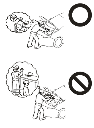
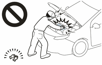
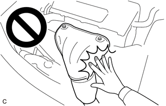
To prevent burns, do not touch the engine, exhaust pipe or other high temperature components while the engine is hot.
.png)
-
To prevent burns, do not touch the engine, exhaust manifold or other high temperature components while the engine is hot.
-
The engine assembly with transaxle is very heavy. Be sure to follow the procedure described in the repair manual, or the engine lifter may suddenly drop or the engine assembly with transaxle may fall off the engine lifter.
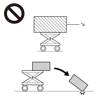
*a
An Object Exceeding Weight Limit of Engine Lifter
-
The hybrid vehicle transaxle assembly is very heavy. Be sure to follow the procedure described in the repair manual, or the transmission jack may suddenly drop or a part may fall.
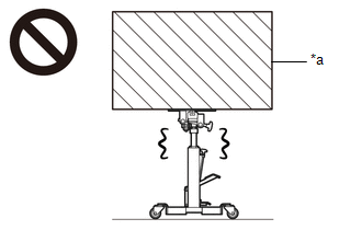
*a
Object Exceeding Weight Limit of Transmission Jack
NOTICE:
- After the engine switch is turned off, the radio receiver assembly records various types of memory and settings. As a result, after turning the engine switch off, make sure to wait at least 85 seconds before disconnecting the cable from the negative (-) battery terminal. (for Audio and Visual System)
- After the engine switch is turned off, the radio receiver assembly records various types of memory and settings. As a result, after turning the engine switch off, make sure to wait at least 85 seconds before disconnecting the cable from the negative (-) battery terminal. (for Navigation System)
PROCEDURE
1. PERFORM RESOLVER INITIALIZATION
NOTICE:
If it is necessary to replace the hybrid vehicle transaxle assembly, make sure to perform resolver initialization before starting work.
Click here
2. REMOVE ENGINE ASSEMBLY WITH TRANSAXLE
Click here
3. REMOVE FUEL DELIVERY GUARD
Click here
4. INSTALL ENGINE HANGERS
Click here
5. REMOVE STEERING GEAR HEAT INSULATOR
Click here
6. DISCONNECT ENGINE WIRE
(a) Remove the 2 bolts.
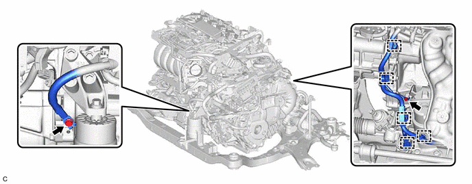
(b) Disengage the 5 clamps.
(c) Disconnect the wire harness connector from the rack and pinion power steering gear assembly.
HINT:
Release the lock before rotating the lock lever.
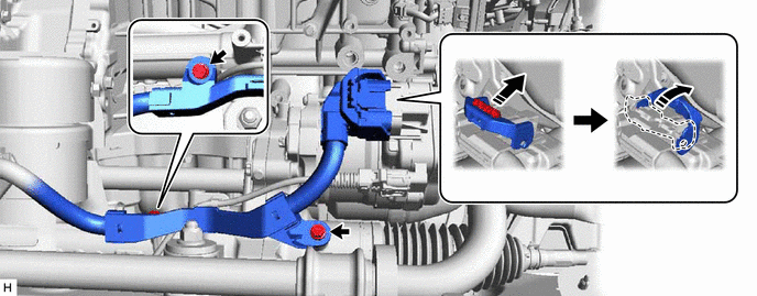
(d) Remove the 2 bolts and separate the wire harness from the rack and pinion power steering gear assembly.
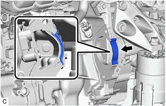
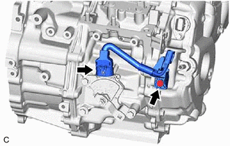
7. DISCONNECT HV AIR CONDITIONING WIRE
| (a) Remove the bolt. |
|
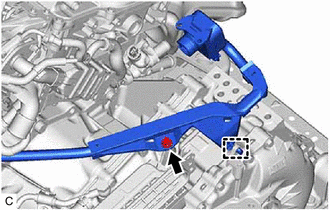
(b) Disengage the guide to disconnect the HV air conditioning wire from the hybrid vehicle transaxle assembly.
8. REMOVE STARTER HOLE INSULATOR
| (a) Remove the 2 bolts and starter hole insulator from the engine assembly. |
|
9. REMOVE FLYWHEEL HOUSING SIDE COVER
| (a) Remove the flywheel housing side cover from the engine assembly. |
|
10. REMOVE FRONT FRAME ASSEMBLY
Click here
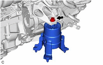
11. REMOVE FRONT ENGINE MOUNTING INSULATOR
| (a) Remove the bolt and front engine mounting insulator from the front engine mounting bracket. |
|
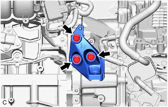
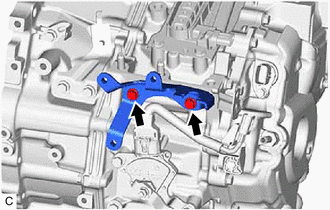
12. REMOVE FRONT ENGINE MOUNTING BRACKET
| (a) Remove the 3 bolts and front engine mounting bracket from the hybrid vehicle transaxle assembly. |
|
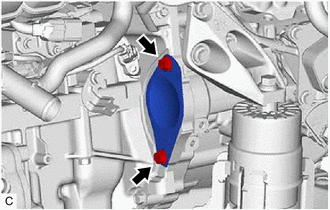
13. REMOVE REAR ENGINE MOUNTING INSULATOR
Click here
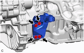
14. REMOVE REAR ENGINE MOUNTING BRACKET
| (a) Remove the 4 bolts and rear engine mounting bracket from the hybrid vehicle transaxle assembly. |
|
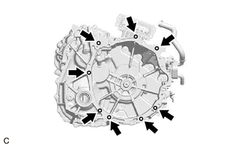
15. REMOVE HYBRID VEHICLE TRANSAXLE ASSEMBLY
| (a) Remove the 8 bolts and hybrid vehicle transaxle assembly from the engine assembly. NOTICE:
|
|
16. REMOVE MOTOR CABLE
Click here
17. REMOVE MOTOR COOLING COOLER
Click here
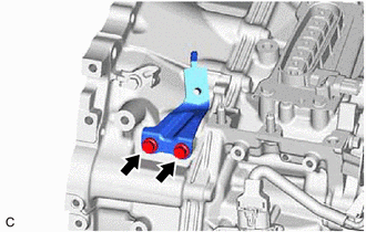
18. REMOVE NO. 1 TRANSMISSION CONTROL CABLE BRACKET
| (a) Remove the 2 bolts and No. 1 transmission control cable bracket from the hybrid vehicle transaxle assembly. |
|
19. REMOVE HOSE BRACKET
| (a) Remove the 2 bolts and hose bracket from the hybrid vehicle transaxle assembly. |
|
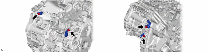
20. REMOVE TRANSMISSION WIRE
| (a) Disconnect the connector. |
|
(b) Remove the bolt and transmission wire from the hybrid vehicle transaxle assembly.
21. REMOVE WIRE HARNESS CLAMP BRACKET
(a) Remove the 4 bolts and 4 wire harness clamp brackets from the hybrid vehicle transaxle assembly.
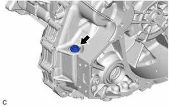
22. REMOVE TRANSAXLE HOUSING PLUG
| (a) Remove the transaxle housing plug and gasket from the hybrid vehicle transaxle assembly. |
|
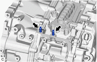
23. REMOVE STUD BOLT
| (a) Using a E8 "TORX" socket wrench, remove the 2 stud bolts from the hybrid vehicle transaxle assembly. |
|
24. REMOVE AUTOMATIC TRANSMISSION CASE COVER
| (a) Remove the 2 bolts. |
|
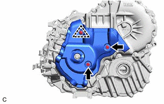
(b) Remove the clip and automatic transmission case cover from the hybrid vehicle transaxle assembly.
READ NEXT:
 Components
COMPONENTS ILLUSTRATION *1 INPUT SHAFT TYPE T OIL SEAL *2 HYBRID VEHICLE TRANSAXLE ASSEMBLY ● Non-reusable part MP grease
Replacement
REPLACEMENT CAUTION / NOTICE / HINT The necessary procedures (adjustment, calibration, initialization, or registration) that must be performed after parts are removed and installed, or replaced during
SEE MORE:
GPS Antenna Connection Malfunction(short) (B15C0,B15C1)
DESCRIPTION These DTCs are stored when a malfunction occurs in the navigation antenna assembly. DTC No. Detection Item DTC Detection Condition Trouble Area B15C0 GPS Antenna Connection Malfunction(short) GPS Antenna Connection Malfunction(short)
Navigation antenna assembly
An
Lost Communication with Blind Spot Monitor Master Module (U0233)
DESCRIPTION This DTC is stored when the blind spot monitor sensor LH judges that there is a communication problem with the blind spot monitor sensor RH. DTC No. Detection Item DTC Detection Condition Trouble Area U0233 Lost Communication with Blind Spot Monitor Master Module The bli
