Lexus ES: Adjustment
ADJUSTMENT
PROCEDURE
1. REMOVE FRONT WHEEL OPENING EXTENSION PAD RH
Click here .gif)
2. REMOVE FRONT WHEEL OPENING EXTENSION PAD LH
Click here
3. REMOVE NO. 1 ENGINE UNDER COVER
Click here
4. REMOVE NO. 2 ENGINE UNDER COVER ASSEMBLY
Click here
5. DRAIN HYBRID TRANSAXLE FLUID
| (a) Using a 10 mm hexagon socket wrench, remove the filler plug and gasket from the hybrid vehicle transaxle assembly. |
|
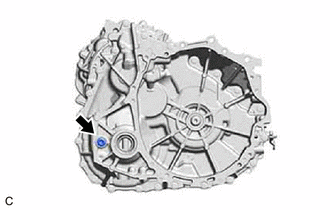
| (b) Using a 10 mm hexagon socket wrench, remove the drain plug and gasket from the hybrid vehicle transaxle assembly and drain the hybrid transaxle fluid. |
|
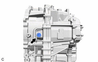
(c) Using a 10 mm hexagon socket wrench, install the drain plug and a new gasket to the hybrid vehicle transaxle assembly.
Torque:
50 N·m {510 kgf·cm, 37 ft·lbf}
(d) Using a 10 mm hexagon socket wrench, temporarily install the filler plug and gasket to the hybrid vehicle transaxle assembly.
HINT:
Reuse the old gasket as the filler plug will be removed again.
6. ADD HYBRID TRANSAXLE FLUID
| (a) Using a 10 mm hexagon socket wrench, remove the filler plug and gasket from the hybrid vehicle transaxle assembly. |
|
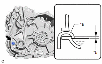
(b) Add hybrid transaxle fluid until the hybrid transaxle fluid level is between 0 to 10 mm (0 to 0.394 in.) from the bottom lip of the filler plug opening. [#]
NOTICE:
- When adding hybrid transaxle fluid, make sure that the vehicle is level.
- Use Toyota Genuine ATF WS.
- Be sure to fully insert the filler nozzle into the filler plug opening.
- Be sure to add hybrid transaxle fluid slowly. If hybrid transaxle fluid is added quickly, the hybrid transaxle fluid may hit internal parts and bounce back, resulting in hybrid transaxle fluid coming out of the filler plug opening.
- Be sure to directly check that the hybrid transaxle fluid level is within the specified range.
- Driving the vehicle with an insufficient or excessive amount of hybrid transaxle fluid may damage the hybrid vehicle transaxle assembly.
Hybrid Transaxle Fluid Standard Capacity (for Reference):
3.9 liters (4.1 US qts, 3.4 Imp. qts)
(c) After adding hybrid transaxle fluid, leave the vehicle for 30 seconds so that the hybrid transaxle fluid surface can become still again, and then check that the hybrid transaxle fluid level is between 0 to 10 mm (0 to 0.394 in.) from the bottom lip of the filler plug opening. (If the hybrid transaxle fluid level is low, repeat this procedure from step [#].)
NOTICE:
After adding hybrid transaxle fluid, make sure to check the hybrid transaxle fluid level.
(d) Using a 10 mm hexagon socket wrench, temporarily install the filler plug and gasket to the hybrid vehicle transaxle assembly.
HINT:
Reuse the old gasket as the filler plug will be removed again.
7. INSPECT HYBRID TRANSAXLE FLUID
Click here
8. INSPECT FOR HYBRID TRANSAXLE FLUID LEAK
9. INSTALL NO. 2 ENGINE UNDER COVER ASSEMBLY
Click here
10. INSTALL NO. 1 ENGINE UNDER COVER
Click here
11. INSTALL FRONT WHEEL OPENING EXTENSION PAD LH
Click here
12. INSTALL FRONT WHEEL OPENING EXTENSION PAD RH
Click here
READ NEXT:
 Components
COMPONENTS ILLUSTRATION *1 FRONT WHEEL OPENING EXTENSION PAD RH *2 FRONT WHEEL OPENING EXTENSION PAD LH *3 NO. 1 ENGINE UNDER COVER *4 NO. 2 ENGINE UNDER COVER ASSEMBLY *5 FI
On-vehicle Inspection
ON-VEHICLE INSPECTION PROCEDURE 1. REMOVE FRONT WHEEL OPENING EXTENSION PAD RH Click here 2. REMOVE FRONT WHEEL OPENING EXTENSION PAD LH Click here 3. REMOVE NO. 1 ENGINE UNDER COVER Click her
Replacement
REPLACEMENT PROCEDURE 1. REMOVE FRONT WHEEL OPENING EXTENSION PAD RH Click here 2. REMOVE FRONT WHEEL OPENING EXTENSION PAD LH Click here 3. REMOVE NO. 1 ENGINE UNDER COVER Click here 4. R
SEE MORE:
Installation
INSTALLATION CAUTION / NOTICE / HINT HINT:
Use the same procedure for the RH side and LH side.
The following procedure is for the LH side.
PROCEDURE 1. INSTALL REAR COMBINATION LIGHT ASSEMBLY (for TMMK Made) 2. INSTALL REAR BUMPER UPPER RETAINER (for TMMK Made) Click here 3. INSTALL REAR B
Steering Angle Sensor Failure (C1626)
DESCRIPTION This DTC is stored if the rear television camera assembly receives a signal via CAN communication from the steering sensor that indicates an internal malfunction. DTC No. Detection Item DTC Detection Condition Trouble Area C1626 Steering Angle Sensor Failure A fail flag
