Lexus ES: Terminals Of Ecu
TERMINALS OF ECU
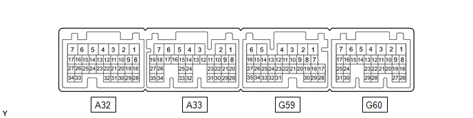
CHECK HYBRID VEHICLE CONTROL ECU
| Terminal No. (Symbol) | Wiring Color | Terminal Description | Condition | Specified Condition |
|---|---|---|---|---|
| A32-15 (STP) - G59-6 (E1) | GR - W-B | Stop light switch signal | Brake pedal depressed | 11 to 14 V |
| Brake pedal released | 0 to 1.5 V | |||
| A33-28 (ST1-) - G59-6 (E1) | LG - W-B | Stop light switch signal | Power switch on (IG), brake pedal depressed | 0 to 1.5 V |
| Power switch on (IG), brake pedal released | 11 to 14 V | |||
| G59-28 (CCS) - G59-6 (E1) | R - W-B | Steering pad switch circuit | Cruise control switch not pushed | 1 MΩ or higher |
| Cruise control main switch pushed | Below 2.5 Ω | |||
| CANCEL switch pushed | 228 to 252 Ω | |||
| +RES switch pushed | 599 to 661 Ω | |||
| -SET switch pushed | 1463 to 1617 Ω |
NOTICE:
- Turning the power switch on (IG) with connectors disconnected may cause DTCs to be stored. Make sure to clear the DTCs after inspection has been performed.
- Do not apply excessive force to the forward recognition camera connector.
CHECK FORWARD RECOGNITION CAMERA
.png)
(a) Measure the voltage and resistance according to the value(s) in the table below.
| Terminal No. (Symbol) | Wiring Color | Terminal Description | Condition | Specified Condition |
|---|---|---|---|---|
| P5-3 (LKSW) - P5-10 (GND) | BE - LA | Steering pad switch assembly signal (distance control signal) | Power switch on (IG), steering pad switch assembly (vehicle-to-vehicle distance control switch) on | Below 1 V |
| Power switch on (IG), steering pad switch assembly (vehicle-to-vehicle distance control switch) off | 4.75 to 5.25 V | |||
| P5-10 (GND) - Body ground | LA - Body ground | Ground | Always | Below 1 Ω |
| P5-7 (IGB) - P5-10 (GND) | LA-P - LA | Power source | Power switch on (IG) | 11 to 14 V |
| Power switch off | Below 1 V |
(b) Check for pulses according to the value(s) in the table below.
HINT:
If the waveform is not similar to that shown in the illustration, a malfunction of a CAN bus line, terminating resistor, or the forward recognition camera is suspected.
| Terminal No. (Symbol) | Wiring Color | Terminal Description | Condition | Specified Condition |
|---|---|---|---|---|
| P5-6 (CANH) - P5-10 (GND) | B - LA | CAN communication signal | Power switch on (IG) | Pulse generation (See waveform 1) |
| P5-12 (CANL) - P5-10 (GND) | W - LA | Pulse generation (See waveform 2) | ||
| P5-5 (CA1P) - P5-10 (GND) | L - LA | Pulse generation (See waveform 1) | ||
| P5-11 (CA1N) - P5-10 (GND) | W - LA | Pulse generation (See waveform 2) |
(1) WAVEFORM 1
.png)
| Item | Content |
|---|---|
| Tester Connection |
|
| Tool Setting | 1 V/DIV., 10 μs/DIV. |
| Condition | Power switch on (IG) |
HINT:
The waveform varies depending on the CAN communication signal.
(2) WAVEFORM 2
.png)
| Item | Content |
|---|---|
| Tester Connection |
|
| Tool Setting | 1 V/DIV., 10 μs/DIV. |
| Condition | Power switch on (IG) |
HINT:
The waveform varies depending on the CAN communication signal.
READ NEXT:
 Diagnosis System
DIAGNOSIS SYSTEM DIAGNOSIS FUNCTION (a) The diagnosis function turns off the cruise control indicator, illuminates the master warning light and displays a warning message when a malfunction is detecte
Dtc Check / Clear
DTC CHECK / CLEAR NOTICE: When the diagnosis system is changed from normal mode to check mode or vice versa, all DTCs and freeze frame data recorded in normal mode are cleared. Before changing modes,
Freeze Frame Data
FREEZE FRAME DATA CHECK FREEZE FRAME DATA HINT: The ECU records vehicle and driving condition information as freeze frame data the moment a DTC is stored. (a) Connect the Techstream to the DLC3. (b) T
SEE MORE:
Poor Engine Power (P319000,P319100)
DESCRIPTION The ECM receives signals from the hybrid vehicle control ECU assembly such as the requested engine torque, target engine speed and engine cranking status, and controls the engine output based on the target engine speed and requested torque. DTC No. Detection Item DTC Detection Con
Definition Of Terms
DEFINITION OF TERMS Term Definition Monitor Description Description of what the hybrid vehicle control ECU monitors and how to detects malfunctions (monitoring purpose and its details). Related DTCs A group of diagnostic trouble codes that are output by the hybrid vehicle control EC
