Lexus ES: Components
COMPONENTS
ILLUSTRATION
.png)
| *1 | FRONT CENTER UPPER SUSPENSION BRACE SUB-ASSEMBLY | - | - |
.png) | Tightening torque for "Major areas involving basic vehicle performance such as moving/turning/stopping": N*m (kgf*cm, ft.*lbf) | .png) | N*m (kgf*cm, ft.*lbf): Specified torque |
| *T1 | Bolt color black: 8.0 N*m (82 kgf*cm, 71 in.*lbf) Bolt color silver: 8.9 N*m (91 kgf*cm, 79 in.*lbf) | - | - |
ILLUSTRATION
.png)
| *1 | NO. 1 INSTRUMENT PANEL UNDER COVER SUB-ASSEMBLY | - | - |
ILLUSTRATION
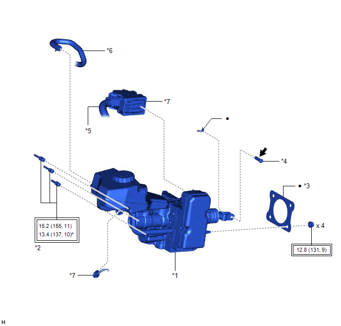
| *1 | BRAKE BOOSTER WITH MASTER CYLINDER ASSEMBLY | *2 | BRAKE LINE |
| *3 | BRAKE MASTER CYLINDER GASKET | *4 | BRAKE PEDAL LINK PIN |
| *5 | ENGINE ROOM MAIN WIRE | *6 | NO. 1 BRAKE ACTUATOR HOSE |
| *7 | CONNECTOR | - | - |
| | Tightening torque for "Major areas involving basic vehicle performance such as moving/turning/stopping": N*m (kgf*cm, ft.*lbf) | * | For use with a union nut wrench |
| ● | Non-reusable part | .png) | Lithium soap base glycol grease |
READ NEXT:
 Installation
INSTALLATION PROCEDURE 1. INSTALL BRAKE MASTER CYLINDER GASKET (a) Install a new brake master cylinder gasket to the brake booster with master cylinder assembly. 2. INSTALL BRAKE BOOSTER WITH MASTER C
Removal
REMOVAL CAUTION / NOTICE / HINT The necessary procedures (adjustment, calibration, initialization, or registration) that must be performed after parts are removed, installed, or replaced during brake
SEE MORE:
Components
COMPONENTS ILLUSTRATION *1 COURTESY LIGHT ASSEMBLY *2 REAR DOOR TRIM BOARD SUB-ASSEMBLY *3 REAR DOOR UPPER TRIM PAD *4 REAR POWER WINDOW REGULATOR SWITCH ASSEMBLY WITH REAR DOOR UPPER ARMREST BASE PANEL ILLUSTRATION *A w/ Rear Door Sunshade - - *1 CURTAIN HOOK
Right Rear Wheel Speed Sensor Signal Stuck Low (C051223)
DESCRIPTION Refer to DTC C051212 Click here DTC No. Detection Item DTC Detection Condition Trouble Area C051223 Right Rear Wheel Speed Sensor Signal Stuck Low
When the vehicle is driven from 0 km/h to 12 km/h (0 mph to 7 mph), the wheel speed is 1.8 km/h (1.1 mph) or less for 0
