Lexus ES: Components
COMPONENTS
ILLUSTRATION
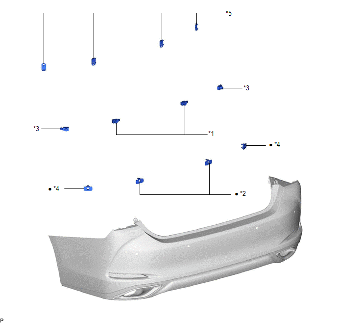
| *1 | REAR CENTER ULTRASONIC SENSOR | *2 | REAR CENTER ULTRASONIC SENSOR RETAINER |
| *3 | REAR CORNER ULTRASONIC SENSOR | *4 | REAR CORNER ULTRASONIC SENSOR RETAINER |
| *5 | ULTRASONIC SENSOR CLIP | - | - |
| ● | Non-reusable part | - | - |
ILLUSTRATION
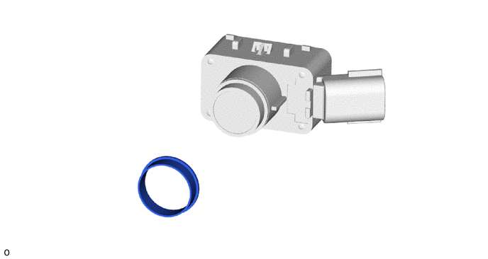
| *1 | ULTRASONIC SENSOR CUSHION SET | - | - |
READ NEXT:
 Inspection
INSPECTION PROCEDURE 1. INSPECT REAR CENTER ULTRASONIC SENSOR (a) Measure the resistance according to the value(s) in the table below. Standard Resistance: Tester Connection Condition Speci
Installation
INSTALLATION PROCEDURE 1. INSTALL ULTRASONIC SENSOR CUSHION SET HINT: Only perform this procedure when removing and installing the ultrasonic sensor cushion set. (a) Install the ultrasonic sensor cush
Removal
REMOVAL CAUTION / NOTICE / HINT The necessary procedures (adjustment, calibration, initialization, or registration) that must be performed after parts are removed and installed, or replaced during ult
SEE MORE:
Rear Left Sensor Malfunction (C1AE6)
DESCRIPTION The rear corner ultrasonic sensor LH is installed to the rear bumper. The clearance warning ECU assembly detects obstacles based on signals received from the rear corner ultrasonic sensor LH. If the rear corner ultrasonic sensor LH has an open circuit or other malfunction, it will not fu
Components
COMPONENTS ILLUSTRATION *1 MOTOR CABLE *2 CONNECTOR COVER *3 TERMINAL CAP - - Tightening torque for "Major areas involving basic vehicle performance such as moving/turning/stopping": N*m (kgf*cm, ft.*lbf) N*m (kgf*cm, ft.*lbf): Specified torque ● Non-reusable
© 2016-2026 Copyright www.lexguide.net
