Lexus ES: Removal
REMOVAL
CAUTION / NOTICE / HINT
The necessary procedures (adjustment, calibration, initialization, or registration) that must be performed after parts are removed and installed, or replaced during rear television camera assembly removal/installation are shown below.
Necessary Procedure After Parts Removed/Installed/Replaced (for HV Model)| Replaced Part or Performed Procedure | Necessary Procedure | Effect/Inoperative Function When Necessary Procedures are not Performed | Link |
|---|---|---|---|
| Rear television camera assembly | w/ Parking Assist Monitor System
| Parking Assist Monitor System | |
| w/ Panoramic View Monitor System
| Panoramic View Monitor System | |
| Replaced Part or Performed Procedure | Necessary Procedure | Effect/Inoperative Function When Necessary Procedures are not Performed | Link |
|---|---|---|---|
| Rear television camera assembly | w/ Parking Assist Monitor System
| Parking Assist Monitor System | |
| w/ Panoramic View Monitor System
| Panoramic View Monitor System | |
PROCEDURE
1. REMOVE LUGGAGE COMPARTMENT DOOR OUTSIDE GARNISH SUB-ASSEMBLY
Click here .gif)
2. REMOVE TELEVISION CAMERA ASSEMBLY WITH WIRE
| (a) Disconnect the connector. |
|
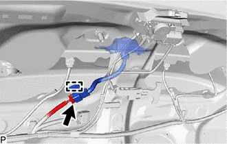
(b) Disengage the clamp.
(c) Disengage the 2 claws to remove the television camera assembly with wire as shown in the illustration.
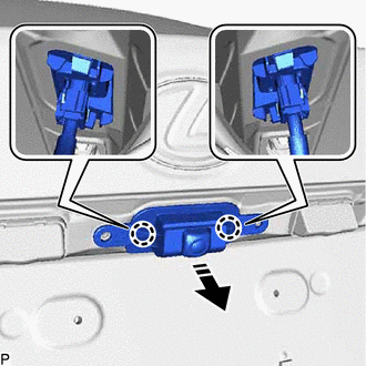
.png) | Remove in this Direction |
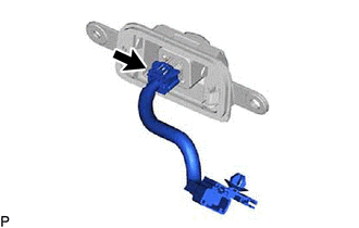
3. REMOVE TELEVISION CAMERA WIRE
| (a) Disconnect the connector to remove the television camera wire. |
|
4. REMOVE REAR TELEVISION CAMERA ASSEMBLY
READ NEXT:
 Components
COMPONENTS ILLUSTRATION *1 FRONT CENTER ULTRASONIC SENSOR *2 FRONT CORNER ULTRASONIC SENSOR *3 FRONT CORNER ULTRASONIC SENSOR RETAINER - - ● Non-reusable part - - IL
Inspection
INSPECTION PROCEDURE 1. INSPECT FRONT CENTER ULTRASONIC SENSOR (a) Measure the resistance according to the value(s) in the table below. Standard Resistance: Tester Connection Condition Spec
SEE MORE:
Disassembly
DISASSEMBLY PROCEDURE 1. REMOVE FRONT DISC BRAKE PISTON (a) Place a piece of cloth between the front disc brake piston and front disc brake cylinder. *a Cloth (b) Apply compressed air to remove the front disc brake piston from the front disc brake cylinder. CAUTION:
Do
Open in Bus 3 Main Bus Line
DESCRIPTION There may be an open circuit in one of the CAN main bus lines when the resistance between terminals 6 (CA3H) and 21 (CA3L) of the central gateway ECU (network gateway ECU) is 70 Ω or higher. Symptom Trouble Area Resistance between terminals 6 (CA3H) and 21 (CA3L) of the central
