Lexus ES: Parts Location
Lexus ES (XZ10) Service Manual / Engine & Hybrid System / A25a-fxs (fuel) / Fuel System / Parts Location
PARTS LOCATION
ILLUSTRATION
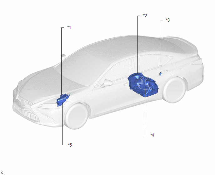
| *1 | ECM | *2 | FUEL TANK ASSEMBLY |
| *3 | FUEL PUMP CONTROL ECU | *4 | FUEL SUCTION TUBE WITH PUMP AND GAUGE ASSEMBLY - FUEL PUMP (for Low Pressure) - FUEL SENDER GAUGE ASSEMBLY - FUEL MAIN VALVE ASSEMBLY |
| *5 | NO. 1 ENGINE ROOM RELAY BLOCK ASSEMBLY AND NO. 1 ENGINE ROOM JUNCTION BLOCK ASSEMBLY - EFI-MAIN NO. 2 RELAY - IG2 NO. 1 RELAY - INJ FUSE | - | - |
ILLUSTRATION
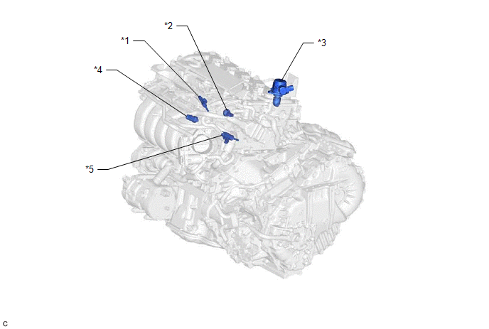
| *1 | PORT FUEL INJECTOR ASSEMBLY | *2 | NO. 2 FUEL PRESSURE SENSOR (for Low Pressure) |
| *3 | FUEL PUMP ASSEMBLY (for High Pressure) | *4 | FUEL PRESSURE SENSOR (for High Pressure) |
| *5 | DIRECT FUEL INJECTOR ASSEMBLY | - | - |
READ NEXT:
 System Diagram
SYSTEM DIAGRAM HIGH PRESSURE SIDE FUEL SYSTEM WIRING DIAGRAM LOW PRESSURE SIDE FUEL SYSTEM WIRING DIAGRAM
On-vehicle Inspection
ON-VEHICLE INSPECTION PROCEDURE 1. CHECK FUEL PUMP OPERATION AND INSPECT FOR FUEL LEAK (a) Check fuel pump operation. (1) Connect the Techstream to the DLC3. (2) Turn the power switch on (IG). NOTICE:
SEE MORE:
Installation
INSTALLATION PROCEDURE 1. INSTALL CAMSHAFT TIMING GEAR BOLT (a) Make sure that the No. 1 cylinder is at TDC/compression. HINT: Check that the cutout of the camshaft timing gear assembly is at the top and align the timing mark (cutout) of the crankshaft pulley with the timing mark on the timing chain
Removal
REMOVAL CAUTION / NOTICE / HINT The necessary procedures (adjustment, calibration, initialization or registration) that must be performed after parts are removed and installed, or replaced during steering column assembly removal/installation are shown below. Necessary Procedures After Parts Removed/
© 2016-2026 Copyright www.lexguide.net
