Lexus ES: Relay
On-vehicle Inspection
ON-VEHICLE INSPECTION
PROCEDURE
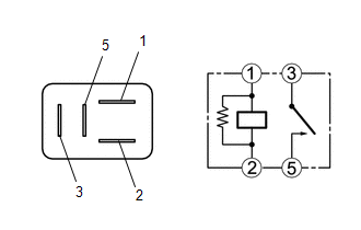
1. INSPECT WIPER RELAY
| (a) Measure the resistance according to the value(s) in the table below. Standard Resistance:
If the result is not as specified, replace the WIPER relay. |
|
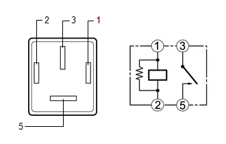
2. INSPECT WASHER RELAY
| (a) Measure the resistance according to the value(s) in the table below. Standard Resistance:
If the result is not as specified, replace the WASHER relay. |
|
READ NEXT:
 Components
COMPONENTS ILLUSTRATION *1 LEVEL WARNING SWITCH ASSEMBLY - -
Removal
REMOVAL CAUTION / NOTICE / HINT The necessary procedures (adjustment, calibration, initialization or registration) that must be performed after parts are removed and installed, or replaced during leve
SEE MORE:
Problem Symptoms Table
PROBLEM SYMPTOMS TABLE HINT:
Use the table below to help determine the cause of problem symptoms. If multiple suspected areas are listed, the potential causes of the symptoms are listed in order of probability in the "Suspected Area" column of the table. Check each symptom by checking the suspect
Yaw Rate Sensor (C1A46)
DESCRIPTION The blind spot monitor sensor receives yaw rate signals from the airbag sensor assembly (yaw rate and acceleration sensor) via CAN communication. Blind Spot Monitor Master DTC No. Detection Item DTC Detection Condition Trouble Area C1A46 Yaw Rate Sensor A fail flag is tr
