Lexus ES: Removal
REMOVAL
CAUTION / NOTICE / HINT
The necessary procedures (adjustment, calibration, initialization or registration) that must be performed after parts are removed and installed, or replaced during level warning switch assembly removal/installation are shown below.
Necessary Procedure After Parts Removed/Installed/Replaced (for HV Model)| Replaced Part or Performed Procedure | Necessary Procedure | Effect/Inoperative Function when Necessary Procedure not Performed | Link |
|---|---|---|---|
| Front bumper assembly |
|
| |
| Front television camera view adjustment | Panoramic View Monitor System (for HV Model) | for Initialization for Calibration |
| Replaced Part or Performed Procedure | Necessary Procedure | Effect/Inoperative Function when Necessary Procedure not Performed | Link |
|---|---|---|---|
| Front bumper assembly |
|
| |
| Front television camera view adjustment | Panoramic View Monitor System (for Gasoline Model) | for Initialization for Calibration |
PROCEDURE
1. REMOVE FRONT BUMPER ASSEMBLY
Click here .gif)
2. DRAIN WASHER FLUID
Click here
3. REMOVE LEVEL WARNING SWITCH ASSEMBLY
(a) Disconnect the connector.
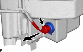
.png) | Remove in this Direction |
(b) Remove the level warning switch assembly as shown in the illustration.
READ NEXT:
 Inspection
INSPECTION PROCEDURE 1. INSPECT LEVEL WARNING SWITCH ASSEMBLY HINT: This check should be performed with the level warning switch assembly installed to the washer jar. (a) Fill the washer jar with w
Installation
INSTALLATION PROCEDURE 1. INSTALL LEVEL WARNING SWITCH ASSEMBLY (a) Install the level warning switch assembly as shown in the illustration. *a Protrusion *b Marking Install in this
SEE MORE:
Diagnostic Trouble Code Chart
DIAGNOSTIC TROUBLE CODE CHART Panoramic View Monitor System DTC No. Detection Item DTC Detection Condition Link C1611 ECU Malfunction When any of the following conditions is met:
EEPROM status (Initial read) malfunction
CPU communication malfunction
Video output malfunction
Display Disconnected (B15D6)
DESCRIPTION The multi-display assembly and radio receiver assembly are connected by AVC-LAN communication lines. This DTC is stored when an AVC-LAN communication error occurs between the multi-display assembly and radio receiver assembly. DTC No. Detection Item DTC Detection Condition Troub
