Lexus ES: Relay
On-vehicle Inspection
ON-VEHICLE INSPECTION
PROCEDURE
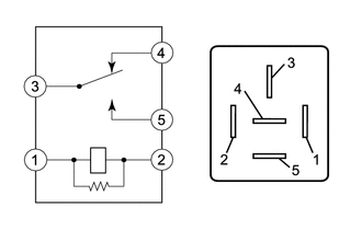
1. INSPECT DEF RELAY
| (a) Measure the resistance according to the value(s) in the table below. Standard Resistance:
If the result is not as specified, replace the DEF relay. |
|
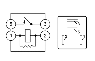
2. INSPECT DEICER RELAY
| (a) Measure the resistance according to the value(s) in the table below. Standard Resistance:
If the result is not as specified, replace the deicer relay. |
|
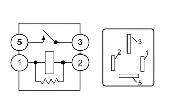
3. INSPECT HWD RELAY
| (a) Measure the resistance according to the value(s) in the table below. Standard Resistance:
If the result is not as specified, replace the HWD relay. |
|
READ NEXT:
 Precaution
PRECAUTION PRECAUTION FOR DISCONNECTING CABLE FROM NEGATIVE BATTERY TERMINAL NOTICE: When disconnecting the cable from the negative (-) battery terminal, initialize the following systems after the cab
Parts Location
PARTS LOCATION ILLUSTRATION *1 DEF RELAY *2 REAR WINDOW DEFOGGER WIRE *3 NO. 1 ENGINE ROOM RELAY BLOCK AND NO. 1 JUNCTION BLOCK ASSEMBLY - DEF FUSE *4 BACK WINDOW GLASS ILLUSTRA
SEE MORE:
Vehicle Control History
VEHICLE CONTROL HISTORY NOTICE: When checking the Vehicle Control History, make sure to record the output codes. Then, clear the Vehicle Control History (RoB) and check it again. CHECK VEHICLE CONTROL HISTORY (FRONT RADAR SENSOR SYSTEM) (a) Connect the Techstream to the DLC3. (b) Turn the power swit
Lost Communication with ECM/PCM "A" Missing Message (U010087,U012587,U012687,U012987,U015587,U110687)
DESCRIPTION The forward recognition camera communicates with each sensor and ECU via CAN communication. If any malfunction is detected in a CAN communication circuit, one or more CAN communication system DTCs are stored. DTC No. Detection Item DTC Detection Condition Trouble Area MIL DT
