Lexus ES: Reassembly
REASSEMBLY
PROCEDURE
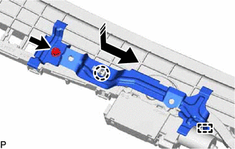
1. INSTALL ROOF WIND DEFLECTOR PANEL SUB-ASSEMBLY
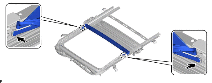
(a) Move the roof wind deflector panel sub-assembly in the direction indicated by the arrow (1) shown in the illustration to engage the 2 guides and install the roof wind deflector panel sub-assembly.
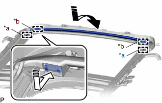
| *a | Guide |
| *b | Spring |
.png) | Install in this Direction (1) |
.png) | Install in this Direction (2) |
(b) Push each spring in the direction indicated by the arrow (2) shown in the illustration to engage the 2 springs.
NOTICE:
Make sure that the springs are securely engaged.
2. INSTALL SLIDING ROOF DRIVE CABLE SUB-ASSEMBLY
NOTICE:
Perform this procedure only when replacement of the sliding roof drive cable sub-assembly is necessary.
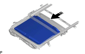
(a) Hold down the roof wind deflector panel sub-assembly.
.png)
.png) | Hold Position |
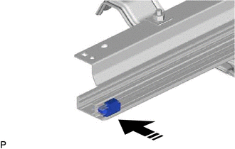
(b) Using a screwdriver, slide the sliding roof drive cable LH as shown in the illustration to install it.
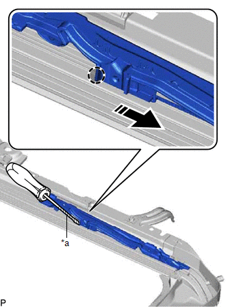
| *a | Protective Tape |
| | Push Position |
| | Install in this Direction |
HINT:
- Tape the screwdriver tip before use.
- Use the same procedure for the RH side.
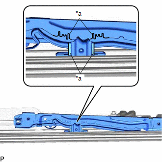
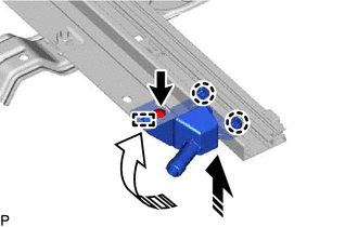
| (c) Adjust Fully Closed Position: (1) Using a screwdriver, slide the sliding roof drive cable LH in either direction and align the alignment marks as shown in the illustration. HINT: Use the same procedure for the RH side. |
|
3. INSTALL REAR ROOF DRIP CHANNEL
(a) Insert the rear roof drip channel into the sliding roof housing sub-assembly as shown in the illustration.
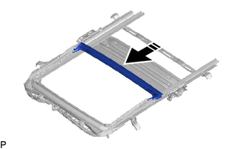
| | Install in this Direction |
(b) Engage the 2 claws as shown in the illustration to install the rear roof drip channel.
| | Install in this Direction | - | - |
4. INSTALL SUNSHADE TRIM SUB-ASSEMBLY
(a) Insert the sunshade trim sub-assembly into the sliding roof housing sub-assembly as shown in the illustration to install it.
| | Install in this Direction |
(b) Install the rear sliding roof sunshade stopper as shown in the illustration.
| | Install in this Direction |
HINT:
Use the same procedure for the RH side.
(c) Move the sliding roof piece sub-assembly LH in the direction indicated by the arrow (1) shown in the illustration to engage the 2 claws.
| | Install in this Direction (1) |
| | Install in this Direction (2) |
HINT:
Use the same procedure for the RH side.
(d) Move the sliding roof piece sub-assembly LH in the direction indicated by the arrow (2) shown in the illustration to engage the guide.
HINT:
Use the same procedure for the RH side.
(e) Install the sliding roof piece sub-assembly LH with the screw.
HINT:
Use the same procedure for the RH side.
5. INSTALL SLIDING ROOF DRIVE GEAR SUB-ASSEMBLY
(a) Apply MP grease to the gear of the sliding roof drive gear sub-assembly.
| (b) Install the sliding roof drive gear sub-assembly with the 2 bolts. Torque: 5.4 N·m {55 kgf·cm, 48 in·lbf} |
|
.png)
(c) Engage the guide and claw as shown in the illustration.
| | Install in this Direction |
(d) Install the map light bracket with the bolt.
Torque:
5.4 N·m {55 kgf·cm, 48 in·lbf}
READ NEXT:
 Installation
INSTALLATION PROCEDURE 1. INSTALL SLIDING ROOF OR REMOVABLE ROOF HOUSING SUB-ASSEMBLY (a) Loosen the 4 bolts of the brackets of the sliding roof or removable roof housing sub-assembly. (b) Temporaril
Sliding Roof Switch Assembly
ComponentsCOMPONENTS ILLUSTRATION *1 MAP LIGHT ASSEMBLY *2 MAP LIGHT SUB-ASSEMBLY *3 ROOF CONSOLE BOX INNER COVER - - ● Non-reusable part - - InspectionINSPECTION
SEE MORE:
Inspection
INSPECTION PROCEDURE 1. INSPECT FRONT SHOCK ABSORBER ASSEMBLY (a) Compress and extend the front shock absorber assembly rod 4 times or more. Standard: When compressed and extended at a constant speed, the stroke of the shock absorber rod is smooth with no abnormal resistance or sounds. When extende
"A" Camshaft Position Actuator Bank 1 General Electrical Failure (P136001)
DESCRIPTION Refer to DTC P001001. Click here DTC No. Detection Item DTC Detection Condition Trouble Area MIL Memory Note P136001 "A" Camshaft Position Actuator Bank 1 General Electrical Failure While engine is running, malfunction in rotation signal (VTS) of cam timing contr
