Lexus ES: Installation
INSTALLATION
PROCEDURE
1. INSTALL SLIDING ROOF OR REMOVABLE ROOF HOUSING SUB-ASSEMBLY
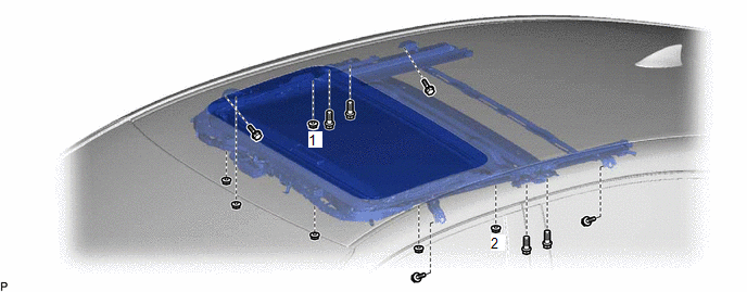
(a) Loosen the 4 bolts of the brackets of the sliding roof or removable roof housing sub-assembly.
(b) Temporarily install the sliding roof or removable roof housing sub-assembly with the 6 nuts and 8 bolts.
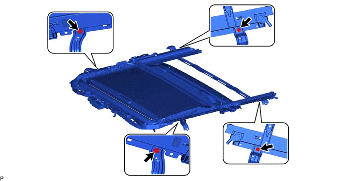
(c) Tighten the 2 nuts.
HINT:
Tighten the 2 nuts in the order shown in the illustration.
Torque:
8.0 N·m {82 kgf·cm, 71 in·lbf}
(d) Tighten the 4 nuts.
Torque:
8.0 N·m {82 kgf·cm, 71 in·lbf}
(e) Tighten the 12 bolts to install the sliding roof or removable roof housing sub-assembly.
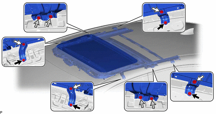
.png) | Bolt (A) | .png) | Bolt (B) |
.png) | Bolt (C) | - | - |
HINT:
- The brackets can be installed in any order.
- Tighten the bolts in the order of (A), (B) and then (C).
Torque:
Bolt (A), (B) :
8.0 N·m {82 kgf·cm, 71 in·lbf}
Bolt (C) :
5.4 N·m {55 kgf·cm, 48 in·lbf}
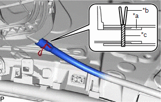
2. CONNECT SLIDING ROOF DRAIN HOSE
HINT:
Use the same procedure for all of the sliding roof drain hoses.
| (a) for Clamp Type: (1) Connect the sliding roof drain hose. HINT: Slide the hose to the base of the drain pipe. (2) Engage the claw to secure the sliding roof drain hose. HINT: Make sure that the clamp is on the marking or between the marking and hose end. |
|
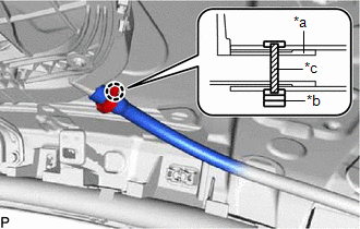
| (b) for Clip Type: (1) Expand the clip to connect the sliding roof drain hose. HINT: Slide the hose to the base of the drain pipe. (2) Release the clip to secure the sliding roof drain hose. NOTICE: The clip must face toward the outside of the vehicle and also be above the lower surface of the sliding roof housing sub-assembly when installing the drain hoses. HINT: Make sure that the clip is on the marking or between the marking and hose end. |
|
3. INSTALL SLIDING ROOF WEATHERSTRIP
(a) Install the sliding roof weatherstrip.
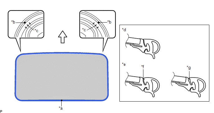
| *a | Joint | *b | Alignment Mark (Blue) |
| *c | Middle Mark | *d | Correct |
| *e | Incorrect | *f | Pinched |
| *g | Gap (raised, wavy, etc.) | - | - |
| | Front Side | - | - |
(1) Position the joint of the sliding roof weatherstrip on the rear side.
(2) Align the alignment marks (Blue) on the sliding roof weatherstrip with the middle marks on the front corners of the sliding roof panel sub-assembly and install the sliding roof weatherstrip.
HINT:
Make sure to install the lip of the sliding roof weatherstrip securely.
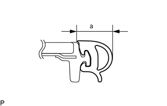
4. INSTALL SLIDING ROOF OR REMOVABLE ROOF PANEL SUB-ASSEMBLY
| (a) Measure the width (a) of the sliding roof weatherstrip. HINT: This measurement will be used in a later step. |
|
(b) Using a T25 "TORX" socket wrench, temporarily install the sliding roof or removable roof panel sub-assembly with the 4 screws.
(c) Perform a level check.
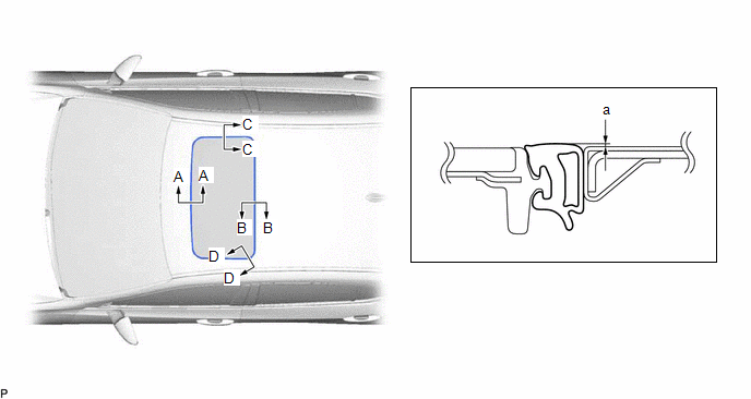
(1) Check the difference in level "a" between the roof panel and the upper surface of the sliding roof weatherstrip when the sliding roof or removable roof panel sub-assembly is fully closed.
HINT:
"+" represents the condition that the glass is above the panel level. "-" represents the condition that the glass is below the panel level.
Standard:
| Area | Measurement | Area | Measurement |
|---|---|---|---|
| A - A | -2.0 to 1.0 mm (-0.0787 to 0.0394 in.) | B - B | -1.0 to 2.0 mm (-0.0394 to 0.0787 in.) |
| C - C | -1.5 to 1.5 mm (-0.0591 to 0.0591 in.) | D - D | -1.0 to 1.5 mm (-0.0394 to 0.0591 in.) |
(d) Check the deformation of the sliding roof weatherstrip.
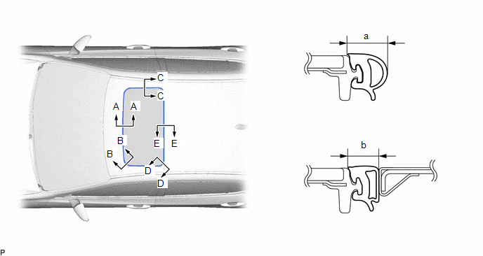
(1) With the sliding roof or removable roof panel sub-assembly in the fully closed position, measure the width (b) of the sliding roof weatherstrip and, using the width (a) measured in step a., calculate the deformation of the sliding roof weatherstrip (a - b).
Standard:
| Area | Measurement | Area | Measurement |
|---|---|---|---|
| A - A | 0.5 to 2.5 mm (0.0197 to 0.0984 in.) | B - B | 0.8 to 2.8 mm (0.0315 to 0.1102 in.) |
| C - C | 0.5 to 2.5 mm (0.0197 to 0.0984 in.) | D - D | 0.8 to 2.8 mm (0.0315 to 0.1102 in.) |
| E - E | 0.5 to 2.5 mm (0.0197 to 0.0984 in.) | - | - |
(e) After adjusting the sliding roof or removable roof panel sub-assembly, using a T25 "TORX" socket wrench, install the sliding roof or removable roof panel sub-assembly with the 4 screws.
Torque:
4.0 N·m {41 kgf·cm, 35 in·lbf}
5. CHECK FOR WATER LEAK
(a) After adjusting the sliding roof or removable roof panel sub-assembly, check for water leakage into the vehicle interior.
(b) If there are any leaks, readjust the sliding roof or removable roof panel sub-assembly.
6. INSTALL CURTAIN SHIELD AIRBAG ASSEMBLY LH
Click here .gif)
7. INSTALL CURTAIN SHIELD AIRBAG ASSEMBLY RH
HINT:
Use the same procedure as for the LH side.
8. INSTALL SLIDING ROOF SIDE GARNISH LH
(a) Engage the 4 claws to install a new sliding roof side garnish LH.
9. INSTALL SLIDING ROOF SIDE GARNISH RH
HINT:
Use the same procedure as for the LH side.
10. INITIALIZE SLIDING ROOF SYSTEM
for Gasoline Model: Click here
for HV Model: Click here
11. CHECK SLIDING ROOF SYSTEM
for Gasoline Model: Click here
for HV Model: Click here
READ NEXT:
 Sliding Roof Switch Assembly
ComponentsCOMPONENTS ILLUSTRATION *1 MAP LIGHT ASSEMBLY *2 MAP LIGHT SUB-ASSEMBLY *3 ROOF CONSOLE BOX INNER COVER - - ● Non-reusable part - - InspectionINSPECTION
Precaution
PRECAUTION PRECAUTION FOR DISCONNECTING CABLE FROM NEGATIVE BATTERY TERMINAL NOTICE: When disconnecting the cable from the negative (-) battery terminal, initialize the following systems after the cab
SEE MORE:
Installation
INSTALLATION PROCEDURE 1. INSTALL NO. 2 CYLINDER HEAD GASKET (a) Place a new No. 2 cylinder head gasket on the cylinder block sub-assembly as shown in the illustration. *a Lot No. Front of Engine NOTICE:
Remove any oil from the contact surfaces.
Make sure to install the No. 2 cy
Installation
INSTALLATION CAUTION / NOTICE / HINT HINT: The parking brake indicator light blinks (red) when the power switch is turned on after replacing the brake actuator assembly. Operate the electric parking brake switch assembly to turn off the parking brake indicator light. PROCEDURE 1. INSTALL BRAKE ACTUA
