Lexus ES: Reassembly
REASSEMBLY
CAUTION / NOTICE / HINT
HINT:
- Use the same procedure for the RH side and LH side.
- The following procedure is for the LH side.
PROCEDURE
1. INSTALL HEADLIGHT SEAL (for TMC Made)
Click here .gif)
2. INSTALL HEADLIGHT BRACKET (for TMC Made)
| (a) Engage the 2 guides. |
|
.png)
(b) Install the headlight bracket with the 2 screws.
(c) Engage the claw to connect the No. 2 headlight cord.
3. INSTALL HEADLIGHT UNIT ASSEMBLY (for TMC Made)
4. INSTALL HEADLIGHT CORD (for TMC Made)
| (a) Engage the 3 clamps to install the headlight cord. |
|
.png)
(b) Connect the connector.
5. INSTALL FRONT SIDE MARKER LIGHT BULB
(a) Install the front side marker light bulb to the headlight cord.
(b) Turn the headlight cord with the front side marker light bulb as shown in the illustration to install them as a unit.
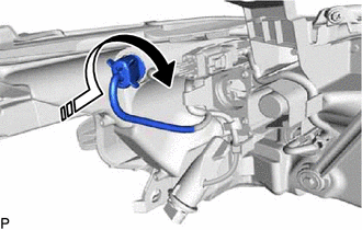
.png) | Install in this Direction |
6. INSTALL FRONT TURN SIGNAL LIGHT BULB
(a) Install the front turn signal light bulb to the headlight cord.
(b) Turn the headlight cord with the front turn signal light bulb as shown in the illustration to install them as a unit.
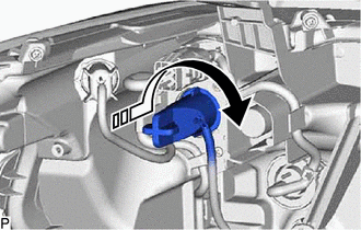
| | Install in this Direction |
7. INSTALL NO. 2 HEADLIGHT FITTING RIM (for TMC Made)
Click here
8. INSTALL HEADLIGHT RIM (for TMC Made)
Click here
9. INSTALL HEADLIGHT GASKET
Click here
10. INSTALL HEADLIGHT ECU SUB-ASSEMBLY
Click here
READ NEXT:
 Installation
INSTALLATION CAUTION / NOTICE / HINT HINT:
Use the same procedure for the RH side and LH side.
The following procedure is for the LH side.
PROCEDURE 1. INSTALL HEADLIGHT ASSEMBLY Click here
Repair
REPAIR CAUTION / NOTICE / HINT HINT:
Use the same procedure for the RH side and LH side.
The following procedure is for the LH side.
If the installation area of the headlight assembly is damage
SEE MORE:
System Diagram
SYSTEM DIAGRAM Transmitting ECU (Transmitter) Receiving ECU Signal Communication Method Skid control ECU (brake actuator assembly) Steering angle sensor Steering angle sensor request signal CAN communication line Steering angle sensor Skid control ECU (brake actuator a
Lost Communication with Front Shade Module (B2346)
DESCRIPTION This DTC is stored when LIN communication between the sliding roof ECU (sliding roof drive gear assembly) and roof sunshade ECU (sliding roof drive gear assembly) stops for 10 seconds or more. DTC No. Detection Item DTC Detection Condition Trouble Area B2346 Lost Communica
