Lexus ES: Reassembly
REASSEMBLY
CAUTION / NOTICE / HINT
HINT:
- Use the same procedure for the RH side and LH side.
- The following procedure is for the LH side.
PROCEDURE
1. PRECAUTION
NOTICE:
After turning the engine switch (for Gasoline Model) or power switch (for HV Model) off, waiting time may be required before disconnecting the cable from the negative (-) auxiliary battery terminal. Therefore, make sure to read the disconnecting the cable from the negative (-) auxiliary battery terminal notices before proceeding with work.
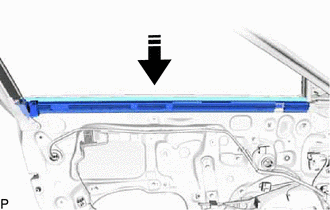
2. INSTALL FRONT DOOR NO. 3 WEATHERSTRIP
| (a) Install the front door No. 3 weatherstrip with the 4 clips. |
|
.png)
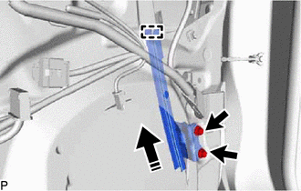
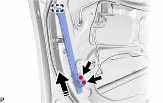
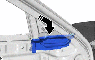
| (b) Install the front door panel sub-assembly with the 4 bolts. Torque: 26 N·m {265 kgf·cm, 19 ft·lbf} NOTICE: To prevent damage, when installing the front door panel sub-assembly, make sure that there are enough people available to hold it securely. |
|
.png)
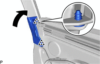
| (c) Using a brush, apply anti-rust coating to the front door hinge assembly as shown in the illustration. |
|

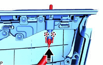
(d) Connect the connector.
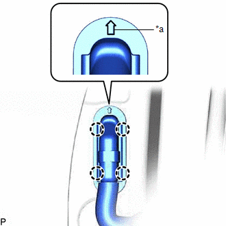
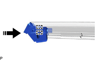
| (e) Engage the 4 claws to install the grommet as shown in the illustration. NOTICE: Install the grommet with the arrow facing up. |
|
3. INSTALL FRONT DOOR SILENCER PAD
(a) Clean the front door panel surface.
(1) Remove any remaining butyl tape from the front door panel.
(2) Wipe off any tape adhesive residue with cleaner.
(b) Remove the release paper from new front door silencer pad.
HINT:
After removing the release paper, keep the exposed adhesive free from foreign matter.
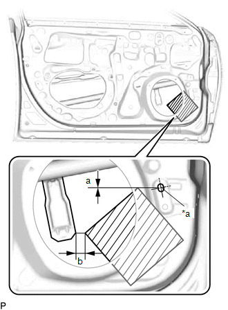
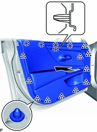
| (c) Install the front door silencer pad as shown in the illustration. Installation Position
|
|
4. REPAIR INSTRUCTION
Click here .gif)
5. INSTALL FRONT INNER BLACK OUT TAPE
Click here
6. INSTALL FRONT DOOR REAR INNER BLACK OUT TAPE
Click here
7. INSTALL FRONT DOOR REAR OUTSIDE SEAL
| (a) Engage the guide to install the front door rear outside seal. |
|
.png)
8. INSTALL FRONT DOOR OUTSIDE MOULDING SUB-ASSEMBLY
Click here
9. INSTALL FRONT DOOR REAR WINDOW FRAME MOULDING
Click here
10. INSTALL FRONT DOOR BELT MOULDING ASSEMBLY
Click here
11. INSTALL FRONT DOOR FRONT LOWER FRAME UPPER COVER
Click here
12. INSTALL FRONT DOOR NO. 2 WEATHERSTRIP
| (a) Engage the 8 clips to install the front door No. 2 weatherstrip. |
|
.png)
13. INSTALL FRONT DOOR PANEL CUSHION
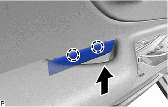
| (a) Engage the 4 claws to install 2 new front door panel cushions. |
|
.png)
14. INSTALL FRONT DOOR WEATHERSTRIP
(a) Clean the front door panel.
(1) Remove any remaining double-sided tape from the front door panel.
(2) Wipe off any tape adhesive residue with cleaner.
(b) Remove the release paper from a new front door weatherstrip.
HINT:
After removing the release paper, keep the exposed adhesive free from foreign matter.
(c) Engage the 23 clips and install a new front door weatherstrip.
.png)
.png) | Double-sided Tape |
15. INSTALL DOOR UPPER FRAME GARNISH
| (a) Engage the 3 claws to install the door upper frame garnish. |
|
.png)
16. INSTALL FRONT DOOR CHECK ASSEMBLY
(a) Clean the bolt hole on the vehicle body.
(b) Clean the threads of the bolt.
(c) Apply adhesive to the threads of the bolt.
Adhesive:
Toyota Genuine Adhesive 1324, Three Bond 1324 or equivalent
(d) Install the front door check assembly with the 2 nuts and bolt.
.png)
.png) | Nut |
.png) | Bolt |
Torque:
Bolt :
29 N·m {296 kgf·cm, 21 ft·lbf}
Nut :
8.0 N·m {82 kgf·cm, 71 in·lbf}
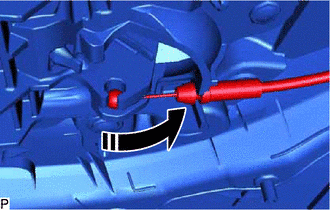
17. INSTALL FRONT DOOR LOCK OPEN ROD
(a) Install the front door lock open rod as shown in the illustration.
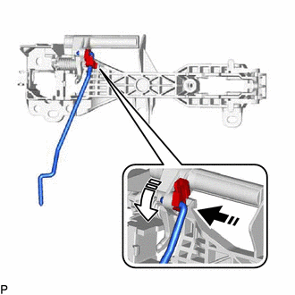
.png) | Install in this Direction (1) |
.png) | Install in this Direction (2) |
18. INSTALL FRONT DOOR OUTSIDE HANDLE FRAME SUB-ASSEMBLY
(a) Apply MP grease to the sliding parts on the front door outside handle frame sub-assembly.
(b) Engage the guide and claw as shown in the illustration.
| | Install in this Direction |
| (c) Using a T30 "TORX" socket wrench, install the front door outside handle frame sub-assembly with the screw. Torque: 4.0 N·m {41 kgf·cm, 35 in·lbf} |
|
.png)
19. INSTALL FRONT DOOR LOCK WITH MOTOR ASSEMBLY
Click here
20. INSTALL FRONT DOOR REAR OUTSIDE HANDLE PAD
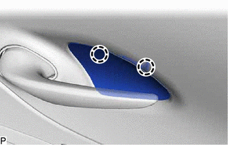
| (a) Engage the 3 guides and claw to install the front door rear outside handle pad. |
|
.png)
21. INSTALL FRONT DOOR FRONT OUTSIDE HANDLE PAD
| (a) Engage the guide and 2 claws to install the front door front outside handle pad. |
|
.png)
22. INSTALL FRONT DOOR OUTSIDE HANDLE COVER (for Front Passenger Side)
| (a) Engage the claw. |
|
.png)
(b) Using a T30 "TORX" socket wrench, install the front door outside handle cover with the screw.
Torque:
4.0 N·m {41 kgf·cm, 35 in·lbf}
| (c) Install the hole plug. |
|
.png)
23. INSTALL FRONT DOOR LOCK CYLINDER ASSEMBLY (for Driver Side)
| (a) Using a T30 "TORX" socket wrench, install the front door lock cylinder assembly with the screw. Torque: 4.0 N·m {41 kgf·cm, 35 in·lbf} |
|
.png)
| (b) Install the hole plug. |
|
.png)
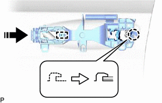
24. INSTALL FRONT DOOR OUTSIDE HANDLE ASSEMBLY
(a) Insert the front end of the front door outside handle assembly into the front door outside handle frame sub-assembly.
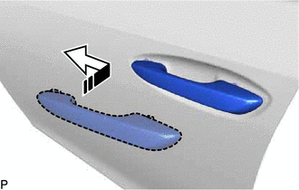
| | Install in this Direction |
(b) Insert the rear end of the front door outside handle assembly into the front door outside handle frame sub-assembly, then slide the front door outside handle assembly toward the front of the vehicle to install it.
(c) Move the lever as shown in the illustration and engage the 2 claws to secure the front door outside handle assembly.
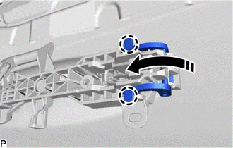
| | Engage in this Direction |
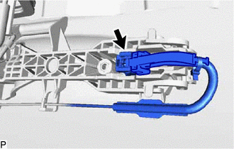
| (d) Engage the 3 clamps. |
|
.png)
| (e) Connect the connector. |
|
(f) Engage the 2 claws as shown in the illustration.
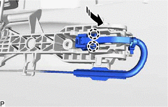
| | Engage in this Direction |
25. INSTALL FRONT DOOR FRONT LOWER FRAME SUB-ASSEMBLY
(a) Engage the guide as shown in the illustration.
| | Install in this Direction |
(b) Install the front door front lower frame sub-assembly with the 2 bolts.
Torque:
8.5 N·m {87 kgf·cm, 75 in·lbf}
26. INSTALL FRONT DOOR REAR LOWER FRAME SUB-ASSEMBLY
(a) Engage the guide as shown in the illustration.
| | Install in this Direction |
(b) Install the front door rear lower frame sub-assembly with the 2 bolts.
Torque:
8.5 N·m {87 kgf·cm, 75 in·lbf}
27. INSTALL FRONT DOOR GLASS RUN
| (a) Install the front door glass run. |
|
.png)
28. INSTALL FRONT DOOR WINDOW REGULATOR ASSEMBLY
(a) Apply MP grease to the sliding parts of the front door window regulator assembly.
(b) Temporarily install the temporary bolt to the front door window regulator assembly.
| (c) Temporarily install the front door window regulator assembly with the 5 bolts. |
|
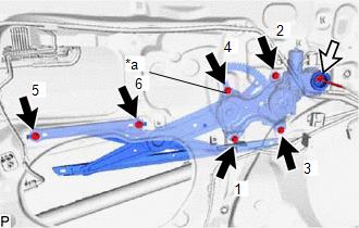
(d) Tighten the temporary bolt and 5 bolts to install the front door window regulator assembly.
HINT:
Tighten the bolts in the order shown in the illustration.
Torque:
8.0 N·m {82 kgf·cm, 71 in·lbf}
(e) Connect the connector.
| (f) Engage the 2 claws to install the front door No. 2 service hole cover. |
|
.png)
29. INSTALL FRONT DOOR GLASS SUB-ASSEMBLY
(a) for Driver Side:
(1) Connect the multiplex network master switch assembly.
(b) for Front Passenger Side:
(1) Connect the power window regulator switch assembly.
(c) Connect the cable to the negative (-) auxiliary battery terminal.
(d) Turn the engine switch (for Gasoline Model) or power switch (for HV Model) on (IG).
(e) Move the front door window regulator assembly so that the door glass bolt holes can be seen.
(f) Turn the engine switch (for Gasoline Model) or power switch (for HV Model) off.
(g) Disconnect the cable from the negative (-) auxiliary battery terminal.
(h) for Driver Side:
(1) Disconnect the multiplex network master switch assembly.
(i) for Front Passenger Side:
(1) Disconnect the power window regulator switch assembly.
(j) Insert the front door glass sub-assembly into the front door panel along the front door glass run as shown in the illustration.
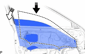
| | Install in this Direction (1) |
| | Install in this Direction (2) |
| (k) Install the front door glass sub-assembly with the 2 bolts. Torque: 5.5 N·m {56 kgf·cm, 49 in·lbf} |
|
.png)
| (l) Install the hole plug. |
|
.png)
30. INSTALL FRONT DOOR PANEL PROTECTOR
(a) Install the front door panel protector as shown in the illustration.
| | Install in this Direction |
31. INSTALL FRONT DOOR VENT SEAL
(a) Engage the 2 guides to install the front door vent seal to the front door inner glass weatherstrip as shown in the illustration.
| | Install in this Direction |
(b) Install the front door inner glass weatherstrip with front door vent seal as shown in the illustration.
| | Install in this Direction |
| (c) Engage the 2 clips to connect the front door weatherstrip as shown in the illustration. |
|
32. INSTALL DOOR SIDE AIRBAG SENSOR
Click here
33. INSTALL FRONT DOOR SERVICE HOLE COVER
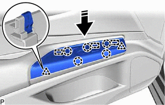
| (a) Engage the 4 clips to install the front door service hole cover. |
|
.png)
| (b) Insert the 3 front door weatherstrip clips and turn them 45 degrees as shown in the illustration to install them. |
|
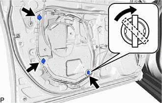
| (c) Engage the 2 clamps. |
|
.png)
34. INSTALL FRONT NO. 1 SPEAKER ASSEMBLY
Click here
35. INSTALL OUTER REAR VIEW MIRROR ASSEMBLY
Click here
36. INSTALL OUTER MIRROR INSTALL HOLE COVER
Click here
37. INSTALL HOLE PLUG
Click here
38. INSTALL OUTER MIRROR CONTROL ECU ASSEMBLY (w/ Memory)
Click here
39. INSTALL FRONT DOOR TRIM BRACKET
| (a) Install the front door trim bracket with the 3 screws. |
|
.png)
40. INSTALL FRONT DOOR LOWER FRAME BRACKET GARNISH
| (a) Engage the 2 clips to install the front door lower frame bracket garnish. |
|
.png)
41. INSTALL FRONT DOOR WIRE (w/o Illumination)
(a) w/ Seat Memory Switch:
| (1) Connect the connector. |
|
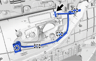
(2) Engage the 3 clamps and claw to install the front door wire.
42. INSTALL FRONT DOOR WIRE (w/ Illumination)
| (a) Connect each connector. |
|
.png)
(b) Engage the clamp to install the front door wire.
43. INSTALL FRONT NO. 4 SPEAKER ASSEMBLY (for 17 Speakers)
Click here
44. INSTALL FRONT DOOR INSIDE HANDLE ILLUMINATION LIGHT ASSEMBLY (w/ Illumination)
Click here
45. INSTALL SEAT MEMORY SWITCH (w/ Seat Memory Switch)
Click here
46. INSTALL FRONT DOOR INSIDE HANDLE SUB-ASSEMBLY
| (a) Install the front door inside handle sub-assembly with the 3 screws. |
|
.png)
47. INSTALL FRONT DOOR TRIM BOARD SUB-ASSEMBLY
(a) Engage the 2 claws as shown in the illustration to connect the front door inside lock/unlock knob locking cable to the front door trim board sub-assembly.
| | Install in this Direction |
(b) Connect the front door lock open lever remote control cable as shown in the illustration.
| | Install in this Direction |
(c) w/ Seat Memory Switch or w/ Illumination:
| (1) Connect the connector. |
|
.png)
(d) for 17 Speakers:
| (1) Connect the connector. |
|
.png)
(e) Engage the guide, 4 claws and 11 clips as shown in the illustration.
| | Install in this Direction |
| (f) Install the front door trim board sub-assembly with the 3 screws. |
|
.png)
| (g) Engage the 2 claws as shown in the illustration. |
|
48. INSTALL COURTESY LIGHT ASSEMBLY
Click here
49. INSTALL MULTIPLEX NETWORK MASTER SWITCH ASSEMBLY WITH FRONT DOOR UPPER ARMREST BASE PANEL (for Driver Side)
(a) Connect the connector.
(b) Engage the 3 guides, 5 claws and 2 clips to install the multiplex network master switch assembly with front door upper armrest base panel as shown in the illustration.
| | Install in this Direction |
50. INSTALL POWER WINDOW REGULATOR SWITCH ASSEMBLY WITH FRONT DOOR UPPER ARMREST BASE PANEL (for Front Passenger Side)
(a) Connect the connector.
(b) Engage the 4 guides, 5 claws and 2 clips to install the power window regulator switch assembly with front door upper armrest base panel as shown in the illustration.

| | Install in this Direction |
51. INSTALL NO. 2 DOOR TRIM PAD
| (a) Engage the 2 claws to install the No. 2 door trim pad. |
|
52. INSTALL BOX BOTTOM MAT (w/ Illumination)
| (a) Install the box bottom mat. |
|
.png)
53. INSTALL DOOR ARMREST COVER
| (a) Install the door armrest cover. |
|
.png)
54. ADJUST FRONT DOOR
Click here
55. CONNECT CABLE TO NEGATIVE AUXILIARY BATTERY TERMINAL
for 2GR-FKS:
Click here
for A25A-FXS:
Click here
56. INITIALIZE POWER WINDOW CONTROL SYSTEM
for Gasoline Model:
Click here
for HV Model:
Click here
57. INSPECT POWER WINDOW OPERATION
for Gasoline Model:
Click here
for HV Model:
Click here
58. PERFORM CALIBRATION (w/ Panoramic View Monitor System)
for Gasoline Model:
Click here
for HV Model:
Click here
59. INSPECT SRS WARNING LIGHT
for Gasoline Model:
Click here
for HV Model:
Click here
READ NEXT:
 Reassembly
REASSEMBLY CAUTION / NOTICE / HINT HINT:
Use the same procedure for the RH side and LH side.
The following procedure is for the LH side.
PROCEDURE 1. PRECAUTION NOTICE: After turning the engin
Components
COMPONENTS ILLUSTRATION *1 FRONT DOOR OPENING TRIM WEATHERSTRIP - -
SEE MORE:
Problem Symptoms Table
PROBLEM SYMPTOMS TABLE NOTICE:
If the auxiliary battery voltage becomes low, auxiliary battery load control will operate in order to ensure sufficient power is supplied to the power steering system. In this case, the windshield deicer system may not operate.
HINT:
Use the table below to hel
Data Signal Circuit between Radio Receiver and Stereo Jack Adapter
DESCRIPTION The No. 1 stereo jack adapter assembly sends the sound data signal or image data signal from a USB device to the radio receiver assembly via this circuit. WIRING DIAGRAM PROCEDURE 1. CHECK HARNESS AND CONNECTOR (RADIO RECEIVER ASSEMBLY - NO. 1 STEREO JACK ADAPTER ASSEMBLY) (a)
