Lexus ES: Rear Window Defogger System does not Operate
DESCRIPTION
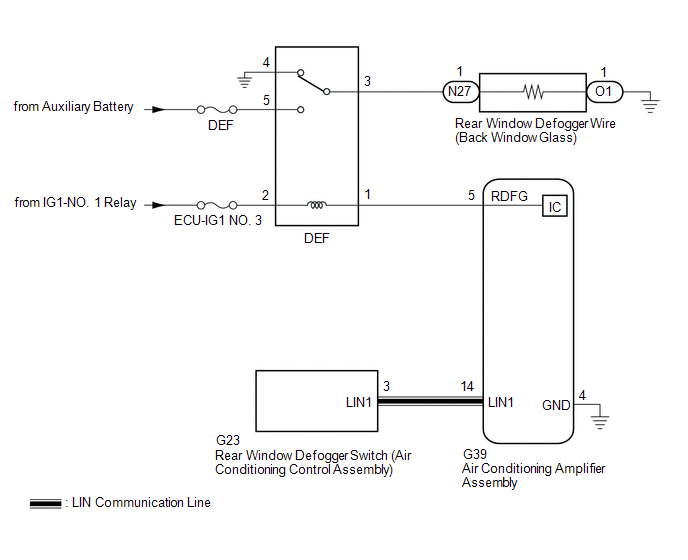
When the rear window defogger switch on the air conditioning control assembly is pressed, the operation signal is transmitted to the air conditioning amplifier assembly via LIN communication. When the air conditioning amplifier assembly receives the signal, it turns on the DEF relay to operate the window defogger system.
WIRING DIAGRAM
CAUTION / NOTICE / HINT
NOTICE:
- Inspect the fuses for circuits related to this system before performing the following procedure.
- If the auxiliary battery voltage becomes low, auxiliary battery load control will operate in order to ensure sufficient power is supplied to the power steering system. In this case, the window defogger system may not operate.
PROCEDURE
| 1. | CHECK AIR CONDITIONING SYSTEM |
(a) Check the air conditioning system.
HINT:
Both the window defogger system operation signal and air conditioning system operation signal are transmitted to the air conditioning amplifier assembly via the same communication line.
OK:
The air conditioning system operates normally.
| NG | .gif) | GO TO AIR CONDITIONING SYSTEM |
|
.gif)
| 2. | PERFORM ACTIVE TEST USING TECHSTREAM |
(a) Connect the Techstream to the DLC3.
(b) Turn the power switch on (IG).
(c) Turn the Techstream on.
(d) Enter the following menus: Body Electrical / Air Conditioner / Active Test.
(e) Perform the Active Test according to the display on the Techstream.
Body Electrical > Air Conditioner > Active Test| Tester Display | Measurement Item | Control Range | Diagnostic Note |
|---|---|---|---|
| Defogger Relay (Rear) | Rear window defogger wire (Back window glass) | OFF or ON | - |
| Tester Display |
|---|
| Defogger Relay (Rear) |
OK:
The window defogger system operates normally.
| NG | | GO TO STEP 4 |
|
| 3. | REPLACE REAR WINDOW DEFOGGER SWITCH (AIR CONDITIONING CONTROL ASSEMBLY) |
(a) Replace the rear window defogger switch (air conditioning control assembly) with a new or known good one.
Click here .gif)
(b) Check that the window defogger system operates normally.
Click here
OK:
The window defogger system operates normally.
| OK | | END (REAR WINDOW DEFOGGER SWITCH (AIR CONDITIONING CONTROL ASSEMBLY) WAS DEFECTIVE) |
| NG | | REPLACE AIR CONDITIONING AMPLIFIER ASSEMBLY |
| 4. | INSPECT DEF RELAY |
(a) Inspect the DEF relay.
Click here
| NG | | REPLACE DEF RELAY |
|
| 5. | CHECK HARNESS AND CONNECTOR (DEF RELAY - IG1-NO. 1 RELAY AND BATTERY) |
| (a) Remove the DEF relay from the No. 1 engine room relay block and No. 1 junction block assembly. |
|
.png)
(b) Measure the voltage according to the value(s) in the table below.
Standard Voltage:
| Tester Connection | Condition | Specified Condition |
|---|---|---|
| DEF relay holder terminal 2 - Body ground | Power switch on (IG) | 11 to 14 V |
| DEF relay holder terminal 5 - Body ground | Always | 11 to 14 V |
| NG | | REPAIR OR REPLACE HARNESS OR CONNECTOR |
|
| 6. | CHECK HARNESS AND CONNECTOR (DEF RELAY - AIR CONDITIONING AMPLIFIER ASSEMBLY) |
| (a) Remove the DEF relay from the No. 1 engine room relay block and No. 1 junction block assembly. |
|
(b) Disconnect the G39 air conditioning amplifier assembly connector.
(c) Measure the resistance according to the value(s) in the table below.
Standard Resistance:
| Tester Connection | Condition | Specified Condition |
|---|---|---|
| DEF relay holder terminal 1 - G39-5 (RDFG) | Always | Below 1 Ω |
| DEF relay holder terminal 1 or G39-5 (RDFG) - Body ground | Always | 10 kΩ or higher |
| NG | | REPAIR OR REPLACE HARNESS OR CONNECTOR |
|
| 7. | CHECK HARNESS AND CONNECTOR (DEF RELAY - REAR WINDOW DEFOGGER WIRE (BACK WINDOW GLASS)) |
| (a) Remove the DEF relay from the No. 1 engine room relay block and No. 1 junction block assembly. |
|
(b) Disconnect the N27 rear window defogger wire (back window glass) wire connector.
(c) Measure the resistance according to the value(s) in the table below.
Standard Resistance:
| Tester Connection | Condition | Specified Condition |
|---|---|---|
| DEF relay holder terminal 3 - N27-1 | Always | Below 1 Ω |
| DEF relay holder terminal 3 or N27-1 - Body ground | Always | 10 kΩ or higher |
| NG | | REPAIR OR REPLACE HARNESS OR CONNECTOR |
|
| 8. | CHECK HARNESS AND CONNECTOR (REAR WINDOW DEFOGGER WIRE (BACK WINDOW GLASS) - BODY GROUND) |
(a) Disconnect the O1 rear window defogger wire (back window glass) connector.
(b) Measure the resistance according to the value(s) in the table below.
Standard Resistance:
| Tester Connection | Condition | Specified Condition |
|---|---|---|
| O1-1 - Body ground | Always | Below 1 Ω |
| NG | | REPAIR OR REPLACE HARNESS OR CONNECTOR |
|
| 9. | CHECK AIR CONDITIONING AMPLIFIER ASSEMBLY |
| (a) Reconnect the G39 air conditioning amplifier assembly connector. |
|
.png)
(b) Reinstall the DEF relay.
(c) Remove the air conditioning amplifier assembly with its connectors still connected.
Click here
(d) Measure the voltage according to the value(s) in the table below.
Standard Voltage:
| Tester Connection | Condition | Specified Condition |
|---|---|---|
| G39-5 (RDFG) - G39-4 (GND) | Power switch on (IG), rear window defogger switch on | Below 1 V |
| G39-5 (RDFG) - G39-4 (GND) | Power switch on (IG), rear window defogger switch off | 11 to 14 V |
| OK | | REPAIR OR REPLACE BACK WINDOW GLASS |
| NG | | REPLACE AIR CONDITIONING AMPLIFIER ASSEMBLY |
READ NEXT:
 Window Defogger Wire
On-vehicle InspectionON-VEHICLE INSPECTION PROCEDURE 1. CHECK REAR WINDOW DEFOGGER OPERATION (a) When the engine switch (for Gasoline Model) or power switch (for HV Model) is on (IG) and the rear win
Precaution
PRECAUTION PRECAUTION FOR DISCONNECTING CABLE FROM NEGATIVE BATTERY TERMINAL NOTICE: When disconnecting the cable from the negative (-) battery terminal, initialize the following systems after the cab
SEE MORE:
Inspection
INSPECTION PROCEDURE 1. INSPECT CYLINDER HEAD SUB-ASSEMBLY (a) Using a precision straightedge and feeler gauge, measure the warpage of the contact surfaces where the cylinder head sub-assembly contacts the cylinder block sub-assembly, intake manifold and exhaust manifold (TWC: Front Catalyst). *
Cylinder 1 Injector "A" Circuit Open (P020113-P020613,P062D13)
DESCRIPTION The D-4S system has two fuel injection systems. One is an in-cylinder direct injection system that directly injects pressurized fuel into the combustion chamber. The other is an intake port injection system. The ECM determines which fuel injection system to use in accordance with the eng
