Lexus ES: Rear Crankshaft Oil Seal
Components
COMPONENTS
ILLUSTRATION
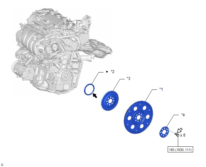
| *1 | DRIVE PLATE AND RING GEAR SUB-ASSEMBLY | *2 | REAR ENGINE OIL SEAL |
| *3 | NO. 1 CRANKSHAFT POSITION SENSOR PLATE | *4 | REAR DRIVE PLATE SPACER |
.png) | N*m (kgf*cm, ft.*lbf): Specified torque | ● | Non-reusable part |
.png) | MP grease | .png) | Adhesive 1324 |
| ★ | Precoated part | - | - |
Installation
INSTALLATION
CAUTION / NOTICE / HINT
NOTICE:
This procedure includes the installation of small-head bolts. Refer to Small-Head Bolts of Basic Repair Hint to identify the small-head bolts.
Click here .gif)
PROCEDURE
1. INSTALL REAR ENGINE OIL SEAL
(a) Using height adjustment attachments and plate lift attachments, place the engine assembly on a flat level surface.
NOTICE:
- Using height adjustment attachments and plate lift attachments, keep the engine assembly level.
- To prevent the No. 2 oil pan sub-assembly from deforming, do not place any attachments under the No. 2 oil pan sub-assembly of the engine assembly.
- Using an engine sling device and engine lift, secure the engine assembly before servicing.
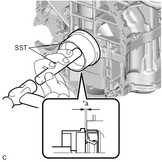
(b) Apply MP grease to the lip of a new rear engine oil seal.
NOTICE:
- Keep the lip free from foreign matter.
- Do not allow MP grease to contact the dust seal.
| (c) Using SST and a hammer, tap in the rear engine oil seal. SST: 09223-15030 SST: 09950-70010 09951-07150 Standard Depth: -0.9 to 1.1 mm (-0.0354 to 0.0433 in.) (From the edge of the cylinder block sub-assembly and stiffening crankcase assembly) NOTICE: Do not tap in the rear engine oil seal at an angle. |
|
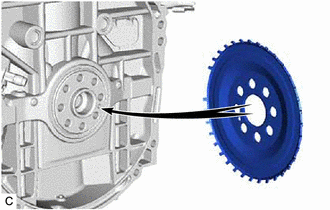
2. INSTALL NO. 1 CRANKSHAFT POSITION SENSOR PLATE
| (a) Install the No. 1 crankshaft position sensor plate. HINT: Align the pin hole of the No. 1 crankshaft position sensor plate with the pin of the crankshaft. |
|
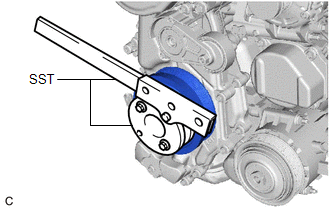
3. INSTALL DRIVE PLATE AND RING GEAR SUB-ASSEMBLY
| (a) Using SST, hold the crankshaft pulley assembly. SST: 09213-54015 SST: 09330-00021 |
|
(b) Clean the 8 bolts and bolt holes.
(c) Install the drive plate and ring gear sub-assembly and rear drive plate spacer to the crankshaft.
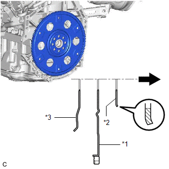
| *1 | Drive Plate and Ring Gear Sub-assembly |
| *2 | Rear Drive Plate Spacer |
| *3 | No. 1 Crankshaft Position Sensor Plate |
.png) | Transaxle Side |
NOTICE:
As the rear drive plate spacer, drive plate and ring gear sub-assembly and No. 1 crankshaft position sensor plate are not reversible, be sure to install them so that they are facing in the direction shown in the illustration.
| (d) Apply adhesive to 2 or 3 threads at the end of each of the 8 bolts. Adhesive: Toyota Genuine Adhesive 1324, Three Bond 1324 or equivalent |
|
.png)
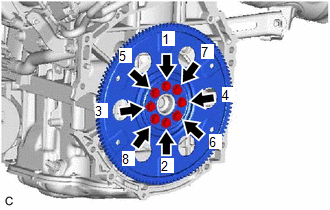
| (e) Install and uniformly tighten the 8 bolts in several steps in the sequence shown in the illustration. Torque: 150 N·m {1530 kgf·cm, 111 ft·lbf} NOTICE: Do not start the engine for at least 1 hour after installing the drive plate and ring gear sub-assembly. |
|
4. INSTALL AUTOMATIC TRANSAXLE ASSEMBLY
Click here
READ NEXT:
 Components
COMPONENTS ILLUSTRATION *1 FUEL DELIVERY PIPE *2 FUEL INJECTOR SEAL *3 DIRECT FUEL INJECTOR ASSEMBLY *4 SENSOR WIRE *5 NO. 3 FUEL INJECTOR BACK-UP RING *6 O-RING *7
SEE MORE:
Stereo Component Amplifier
ComponentsCOMPONENTS ILLUSTRATION *1 AUDIO AMPLIFIER COVER *2 STEREO COMPONENT AMPLIFIER ASSEMBLY WITH BRACKET ILLUSTRATION *A for 10 Speakers *B for 17 Speakers *1 NO. 1 AMPLIFIER BRACKET *2 NO. 2 AMPLIFIER BRACKET *3 STEREO COMPONENT AMPLIFIER ASSEMBLY -
Error in Matching of ECUs (C1567)
DESCRIPTION The power steering ECU (rack and pinion power steering gear assembly) determines whether an incompatible ECM or skid control ECU (brake actuator assembly) is installed based on the identification information. DTC No. Detection Item DTC Detection Condition Trouble Area Warning
