Lexus ES: Components
COMPONENTS
ILLUSTRATION
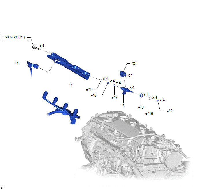
| *1 | FUEL DELIVERY PIPE | *2 | FUEL INJECTOR SEAL |
| *3 | DIRECT FUEL INJECTOR ASSEMBLY | *4 | SENSOR WIRE |
| *5 | NO. 3 FUEL INJECTOR BACK-UP RING | *6 | O-RING |
| *7 | NO. 1 FUEL INJECTOR BACK-UP RING | *8 | NOZZLE HOLDER CLAMP |
| *9 | INJECTOR VIBRATION INSULATOR | *10 | C-RING |
.png) | Tightening torque for "Major areas involving basic vehicle performance such as moving/turning/stopping": N*m (kgf*cm, ft.*lbf) | ● | Non-reusable part |
READ NEXT:
 Inspection
INSPECTION PROCEDURE 1. INSPECT DIRECT FUEL INJECTOR ASSEMBLY NOTICE: This inspection is for checking the direct fuel injector assembly for an open or short. Because the direct fuel injector assembly
Installation
INSTALLATION CAUTION / NOTICE / HINT NOTICE: This procedure includes the installation of small-head bolts. Refer to Small-Head Bolts of Basic Repair Hint to identify the small-head bolts. Click here
SEE MORE:
Diagnostic Trouble Code Chart
DIAGNOSTIC TROUBLE CODE CHART Power Window Control System (for Gasoline Model) DTC No. Detection Item Link B2311 Power Window Motor Malfunction B2311 Power Window Motor Malfunction B2311 Power Window Motor Malfunction B2311 Power Window Motor Malfunction
Headlight Dimmer Switch Circuit
DESCRIPTION The steering sensor receives the following switch information:
Light control switch in DRL OFF*1, off*2, tail, head or AUTO position
Dimmer switch in high, low or high flash (pass) position
*1: w/ DRL OFF Switch
*2: w/o DRL OFF Switch
WIRING DIAGRAM CAUTION / NOTICE / HI
© 2016-2026 Copyright www.lexguide.net
