Lexus ES: Components
COMPONENTS
ILLUSTRATION
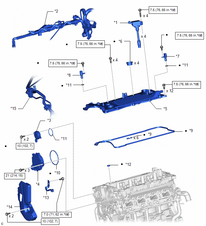
| *1 | IGNITION COIL ASSEMBLY | *2 | ENGINE WIRE |
| *3 | CAM TIMING OIL CONTROL SOLENOID ASSEMBLY | *4 | CAM TIMING CONTROL MOTOR WITH EDU ASSEMBLY |
| *5 | CYLINDER HEAD COVER SUB-ASSEMBLY | *6 | SPARK PLUG TUBE GASKET |
| *7 | CAMSHAFT POSITION SENSOR (for Intake Side) | *8 | CAMSHAFT POSITION SENSOR (for Exhaust Side) |
| *9 | CYLINDER HEAD COVER GASKET | *10 | CAM TIMING CONTROL MOTOR O-RING |
| *11 | O-RING | *12 | CAMSHAFT BEARING CAP OIL HOLE GASKET |
| *13 | NO. 3 BRAKE TUBE CLAMP | *14 | NO. 2 ENGINE COVER |
| *15 | AIR CONDITIONING TUBE AND ACCESSORY ASSEMBLY | - | - |
.png) | N*m (kgf*cm, ft.*lbf): Specified torque | ● | Non-reusable part |
| ★ | Precoated part | - | - |
ILLUSTRATION
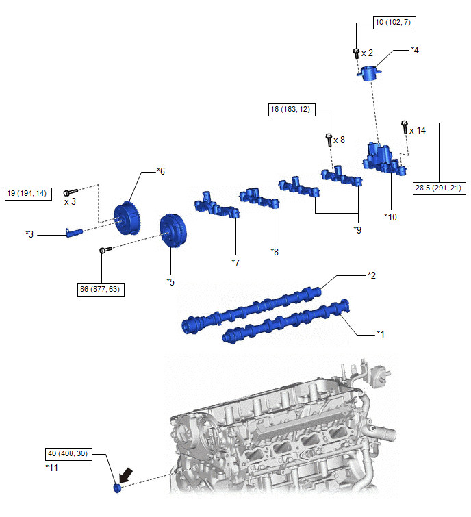
| *1 | CAMSHAFT | *2 | NO. 2 CAMSHAFT |
| *3 | CAMSHAFT TIMING VALVE ASSEMBLY | *4 | FUEL PUMP LIFTER GUIDE |
| *5 | CAMSHAFT TIMING GEAR ASSEMBLY | *6 | CAMSHAFT TIMING EXHAUST GEAR ASSEMBLY |
| *7 | NO. 1 CAMSHAFT BEARING CAP | *8 | NO. 2 CAMSHAFT BEARING CAP |
| *9 | NO. 3 CAMSHAFT BEARING CAP | *10 | NO. 4 CAMSHAFT BEARING CAP |
| *11 | STRAIGHT SCREW PLUG | - | - |
| | N*m (kgf*cm, ft.*lbf): Specified torque | .png) | Adhesive 1324 |
| ★ | Precoated part | - | - |
READ NEXT:
 Installation
INSTALLATION CAUTION / NOTICE / HINT NOTICE: This procedure includes the installation of small-head bolts. Refer to Small-Head Bolts of Basic Repair Hint to identify the small-head bolts. Click here
Precaution
PRECAUTION HINT:
Any digits beyond the 0.01 mm (1/1000 in.) place for standard, minimum and maximum values should be used as a reference only.
When both standard and maximum or minimum values are
SEE MORE:
Pressure Control Solenoid "H" Actuator Stuck Off (P28167F)
DESCRIPTION Based on signals from the transmission revolution sensors (NT and NC), the actual gear is detected. The ECM compares the actual gear with the shift schedule in the ECM memory to detect mechanical malfunctions of the solenoid valves, transmission valve body assembly and automatic transaxl
Removal
REMOVAL PROCEDURE 1. REMOVE FRONT DOOR SCUFF PLATE LH (for LH Side) Click here 2. REMOVE COWL SIDE TRIM BOARD LH (for LH Side) Click here 3. REMOVE NO. 1 INSTRUMENT PANEL UNDER COVER SUB-ASSEMBLY (for LH Side) Click here 4. REMOVE FRONT DOOR OPENING TRIM COVER LH (for LH Side) Click here
