Lexus ES: Precaution
PRECAUTION
PRECAUTION FOR DISCONNECTING CABLE FROM NEGATIVE BATTERY TERMINAL
NOTICE:
When disconnecting the cable from the negative (-) battery terminal, initialize the following system(s) after the cable is reconnected:
| System | See Procedure |
|---|---|
| Lane Control System (for Gasoline Model) | |
| Parking Support Brake System (for Gasoline Model) | |
| Parking Assist Monitor System (for Gasoline Model) | |
| Panoramic View Monitor System (for Gasoline Model) | |
| Pre-collision System (for Gasoline Model) | |
| Power Trunk Lid System (for Gasoline Model) | |
| Lighting System (for Gasoline Model) |
TROUBLESHOOTING PRECAUTION
(a) When there is a malfunction with terminal contact points or part installation problems, removal and installation of the suspected parts may return the system to normal either completely or temporarily.
(b) Before disconnecting a connector or removing and installing a component in order to narrow down the malfunctioning part, make sure to perform the following procedure.
- Check for and record any DTCs and Freeze Frame Data that were stored around the time that the malfunction occurred.
-
If any open circuit DTCs related to intermittent (momentary interruptions) malfunctions are output, check the intermittent monitor.
Click here
.gif)
NOTICE:
Before disconnecting connectors or fuses, turn the engine switch off and wait 20 seconds or more*.
- *: Differs according to vehicle conditions
(c) Since the system may be influenced by malfunctions in systems other than the electronically controlled brake system, be sure to check for DTCs in other systems.
HANDLING PRECAUTION
(a) Always ensure that the engine switch is off before removing the brake actuator assembly or a sensor unless specifically instructed by the repair manual.
(b) When replacing the brake actuator assembly, always replace it with a new one.
NOTICE:
Never use a brake actuator assembly from another vehicle, including new vehicles.
(c) If the brake actuator assembly or a sensor has been removed and installed, always perform a Dealer Mode (Signal Check) inspection and check for DTCs after completion of installation to confirm that the system is operating correctly.
(d) Do not remove and install any electronically controlled brake system components not specified by the repair manual or the system may not operate correctly due to loss of calibration.
(e) When performing diagnosis and repair for the electronically controlled brake system, follow all specified procedures and perform the necessary inspections after completion.
DTC PRECAUTION
(a) If the warning lights are illuminated due to a malfunction, the warning lights will only turn off for some DTCs when the malfunction is repaired and the DTCs are cleared.
(b) If a warning lights are illuminated, it is necessary to follow the procedure to turn off the warning lights.
NOTICE:
- Use caution when operating the vehicle when the warning lights are illuminated as the system may not operate due to a fail-safe function.
- After clearing the DTCs, the DTCs will be stored again if the malfunction persists.
CHASSIS DYNAMOMETER PRECAUTION
When testing with a 2-wheel drum tester such as speedometer tester, combination tester for the speedometer and brakes, or chassis dynamometer, or when jacking up the front wheels and turning the wheels, perform the following procedure to enter Inspection Mode and disable the TRAC and VSC systems.
for entering inspection mode: Click here
CAUTION:
-
Do not use the drum tester with any of the lock chains disconnected.
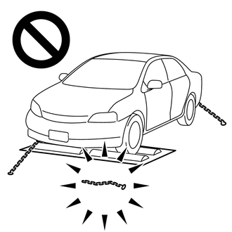
- Using the drum tester with a lock chain disconnected could cause the vehicle to begin moving unexpectedly.
-
Do not use the drum tester while the TRAC or VSC is able to operate.
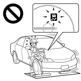
- TRAC or VSC operation could cause the vehicle to begin moving unexpectedly.
DISABLING AND ENABLING OF TRAC AND VSC BY OPERATION OF VSC OFF SWITCH
(a) Switching of mode
Operating the VSC OFF switch switches the system between normal mode, TRAC off mode and VSC off mode.
(1) Normal mode
If the VSC OFF switch is pressed when in TRAC off mode or VSC off mode, the system enters normal mode.
In normal mode, TRAC and VSC are enabled.
The system is set to normal mode when the engine switch is turned on (IG).
(2) TRAC off mode
If the VSC OFF switch is pressed when in normal mode, the system enters TRAC off mode. When in TRAC off mode, TRAC is disabled and the multi-information display in the combination meter assembly displays "Traction Control Turned Off".
When the vehicle reaches a certain vehicle speed when in TRAC off mode, the system automatically returns to normal mode.
(3) VSC off mode
When the VSC OFF switch is pressed and held for 3 seconds or more with the vehicle stopped, the system enters VSC off mode. When in VSC off mode, TRAC and VSC are disabled, the multi-information display in the combination meter assembly displays "Traction Control Turned Off" and the VSC OFF indicator light is illuminated.
The system does not automatically return to normal mode based on vehicle speed when in VSC off mode.
CAN COMMUNICATION SYSTEM PRECAUTION
(a) The CAN communication system is used for communication between the skid control ECU (brake actuator assembly), steering angle sensor, yaw rate and acceleration sensor (airbag ECU assembly) and other ECUs. If there is a malfunction in a CAN communication line, communication DTCs related to the affected systems will be stored.
(b) If any CAN communication DTCs are output, repair the malfunction, then troubleshoot the electronically controlled brake system while communication is normal.
(c) In order to enable CAN communication, a specific type of wiring is used for the CAN communication lines. The wiring used for each communication line is a twisted pair of wires that have an equal length. A bypass wire should not be used because the data being transmitted will be corrupted.
READ NEXT:
 Problem Symptoms Table
PROBLEM SYMPTOMS TABLE If DTCs are not output but the malfunction persists, use the following table to determine which circuits to inspect for each problem symptom. HINT: Refer to each inspection proc
RL Speed Sensor Wrong Installation (X0453)
DESCRIPTION Code Tester Display Measurement Item Trouble Area X0453 RL Speed Sensor Wrong Installation History of rear speed sensor LH being installed incorrectly Rear Speed Sensor
RL Speed Sensor Wrong Installation (X0453)
DESCRIPTION Code Tester Display Measurement Item Trouble Area X0453 RL Speed Sensor Wrong Installation History of rear speed sensor LH being installed incorrectly Rear Speed Sensor
SEE MORE:
Precaution
PRECAUTION PRECAUTION FOR DISCONNECTING CABLE FROM NEGATIVE BATTERY TERMINAL NOTICE:
When disconnecting the cable from the negative (-) battery terminal, initialize the following systems after the cable is reconnected. System Name See Procedure Lane Control System Pre-collisio
Software Incompatibility with Cruise Control Module Invalid/Incompatible Software Component (U030557)
DESCRIPTION The millimeter wave radar sensor assembly receives vehicle information from the forward recognition camera via CAN communication. If the vehicle information stored in the forward recognition camera differs from that stored in the millimeter wave radar sensor assembly, the millimeter wave
