Lexus ES: Power Trunk Lid does not Operate Using Kick Sensor Operation
DESCRIPTION
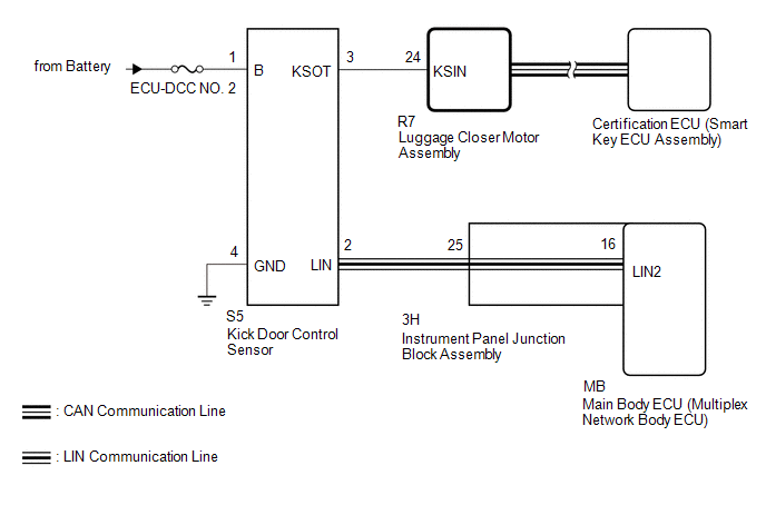
The kick door control sensor receives vehicle speed, IG and ACC signals from the main body ECU (multiplex network body ECU) via LIN communication and uses the information to stop sensor oscillation.
When the kick door control sensor detects a kick operation, it sends an operation signal to the luggage closer motor assembly.
WIRING DIAGRAM
CAUTION / NOTICE / HINT
NOTICE:
- Before troubleshooting, make sure that the kick door control sensor is not damaged.
-
Before troubleshooting, be sure to read Precautions for Hands Free Power Trunk Lid.
Click here
.gif)
-
Before replacing the main body ECU (multiplex network body ECU), refer to Registration.
Click here
-
The power trunk lid system uses the CAN communication system and LIN communication system. First, confirm that there is no malfunction in the CAN communication system and LIN communication system. Refer to the How to Proceed with Troubleshooting procedure.
Click here
-
Before troubleshooting, make sure that the "Kick Sensor Function" customize setting is set to "ON" (initial setting is "ON").
Click here
-
After performing work, using the TECHSTREAM, read the Data List item "Kick Sensor Connection" and check that the kick door control sensor is connected.
Click here
- Inspect the fuses for circuits related to this system before performing the following procedure.
-
If the luggage closer motor assembly has been removed and installed or replaced, or if any of the connectors has been disconnected, initialize the power trunk lid system.
Click here
-
Check that the smart access system (for Entry Function) is normally before performing the following procedure.
Click here
PROCEDURE
| 1. | CHECK FOR DTC |
(a) Connect the Techstream to the DLC3.
(b) Turn the engine switch on (IG).
(c) Turn the Techstream on.
(d) Clear the DTCs.
Body Electrical > Back Door > Clear DTCs(e) Check for DTCs.
Body Electrical > Back Door > Trouble CodesOK:
DTC is not output.
| NG | .gif) | GO TO DIAGNOSTIC TROUBLE CODE CHART |
|
.gif)
| 2. | READ VALUE USING TECHSTREAM |
(a) Enter the following menus: Body Electrical / Back Door / Data List.
(b) Read the Data List according to the display on the Techstream.
Body Electrical > Back Door > Data List| Tester Display | Measurement Item | Range | Normal Condition | Diagnostic Note |
|---|---|---|---|---|
| Kick Sensor Error | Status of the kick door control sensor error | Normal or Error | Normal: Kick door control sensor is normal Error: Kick door control sensor is abnormal | - |
| Tester Display |
|---|
| Kick Sensor Error |
OK:
On the Techstream, Normal is displayed.
| NG | | REPLACE KICK DOOR CONTROL SENSOR |
|
| 3. | READ VALUE USING TECHSTREAM |
(a) Read the Data List according to the display on the Techstream.
Click here
| Tester Display | Measurement Item | Range | Normal Condition | Diagnostic Note |
|---|---|---|---|---|
| Kick Sensor Detection | Status of the kick door control sensor detection | OFF or ON | OFF: Kick door control sensor not detecting a foot ON: Kick door control sensor detecting a foot | - |
| Tester Display |
|---|
| Kick Sensor Detection |
OK:
The Data List item changes according to the detection of the kick door control sensor.
| NG | | GO TO STEP 6 |
|
| 4. | CHECK HARNESS AND CONNECTOR (KICK DOOR CONTROL SENSOR - INSTRUMENT PANEL JUNCTION BLOCK ASSEMBLY) |
(a) Disconnect the S5 kick door control sensor connector.
(b) Disconnect the 3H instrument panel junction block assembly connector.
(c) Measure the resistance according to the value(s) in the table below.
Standard Resistance:
| Tester Connection | Condition | Specified Condition |
|---|---|---|
| S5-2 (LIN) - 3H-25 | Always | Below 1 Ω |
| NG | | REPAIR OR REPLACE HARNESS OR CONNECTOR |
|
| 5. | CHECK INSTRUMENT PANEL JUNCTION BLOCK ASSEMBLY |
(a) Remove the instrument panel junction block assembly.
Click here
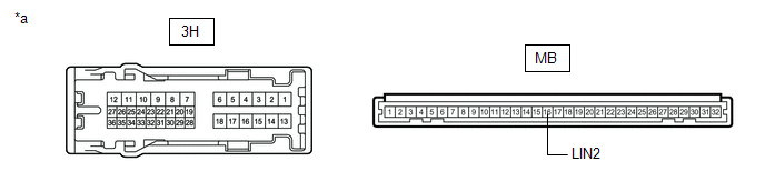
| *a | Component without harness connected (Instrument Panel Junction Block Assembly) | - | - |
(b) Remove the main body ECU (multiplex network body ECU) from instrument panel junction block assembly.
Click here
(c) Measure the resistance according to the value(s) in the table below.
Standard Resistance:
| Tester Connection | Condition | Specified Condition |
|---|---|---|
| 3H-25 - MB-16(LIN2) | Always | Below 1 Ω |
| OK | | REPLACE KICK DOOR CONTROL SENSOR |
| NG | | REPLACE INSTRUMENT PANEL JUNCTION BLOCK ASSEMBLY |
| 6. | CHECK HARNESS AND CONNECTOR (KICK DOOR CONTROL SENSOR - BATTERY AND BODY GROUND) |
(a) Disconnect the S5 kick door control sensor connector.
(b) Measure the voltage according to the value(s) in the table below.
Standard Resistance:
| Tester Connection | Condition | Specified Condition |
|---|---|---|
| S5-4 (GND) - Body ground | Always | Below 1 Ω |
(c) Measure the voltage according to the value(s) in the table below.
Standard Resistance:
| Tester Connection | Condition | Specified Condition |
|---|---|---|
| S5-1 (B) - Body ground | Always | 11 to 14 V |
| NG | | REPAIR OR REPLACE HARNESS OR CONNECTOR |
|
| 7. | CHECK HARNESS AND CONNECTOR (KICK DOOR CONTROL SENSOR - LUGGAGE CLOSER MOTOR ASSEMBLY) |
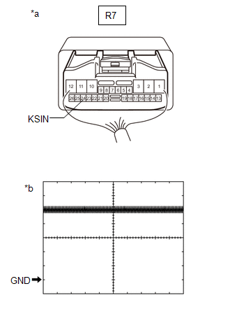
(a) Disconnect the R7 luggage closer motor assembly connector.
(b) Measure the resistance according to the value(s) in the table below.
Standard Resistance:
| Tester Connection | Condition | Specified Condition |
|---|---|---|
| S5-3 (KSOT) - R7-24 (KSIN) | Always | Below 1 Ω |
| S5-3 (KSOT) or R7-24 (KSIN) - Body ground | Always | 10 kΩ or higher |
| NG | | REPAIR OR REPLACE HARNESS OR CONNECTOR |
|
| 8. | CHECK LUGGAGE CLOSER MOTOR ASSEMBLY |
(a) Remove the luggage closer motor assembly with the connector(s) still connected.
Click here
| (b) Check the signal waveform according to the condition(s) in the table below. Measurement Condition
OK: The waveform displayed is as shown in the illustration. |
|
| OK | | REPLACE KICK DOOR CONTROL SENSOR |
| NG | | REPLACE LUGGAGE CLOSER MOTOR ASSEMBLY |
READ NEXT:
 Power Trunk Lid does not Operate Using Outside Switch
DESCRIPTION The door control switch signal is sent to the luggage closer motor assembly. If the power trunk lid does not operate using the door control switch, a door control switch circuit malfunctio
Precaution
PRECAUTION PRECAUTION FOR DISCONNECTING CABLE FROM NEGATIVE AUXILIARY BATTERY TERMINAL NOTICE: When disconnecting the cable from the negative (-) auxiliary battery terminal, initialize the following s
SEE MORE:
Display Malfunction (B15A6,B15B0)
DESCRIPTION These DTCs are stored when a malfunction occurs in the multi-display assembly. DTC No. Detection Item DTC Detection Condition Trouble Area B15A6 Display Malfunction When any of the following conditions is met:
RAM error
Drawing controller malfunction
Internal hard
Lexus Climate Concierge
Lexus Climate Concierge
The seat heaters (if equipped), seat
ventilators (if equipped) and heated
steering wheel (if equipped) are
each automatically controlled
according to the set temperature of
the air conditioning system, the outside
and cabin temperature, etc.
Lexus Climate Concierge
