Lexus ES: PIG Power Supply Voltage (C1552,C1554)
DESCRIPTION
When a malfunction is detected in the PIG power source and power supply relay system, the fail-safe function suspends power assist.
| DTC No. | Detection Item | DTC Detection Condition | Trouble Area | Warning Indicate | Return-to-normal Condition | Note |
|---|---|---|---|---|---|---|
| C1552 | PIG Power Supply Voltage | PIG power source circuit malfunction |
| EPS warning light: Comes on | Power switch is turned on (IG) again | - |
| C1554 | Power Supply Relay Failure | Power source relay circuit malfunction |
| EPS warning light: Comes on | Power switch is turned on (IG) again | - |
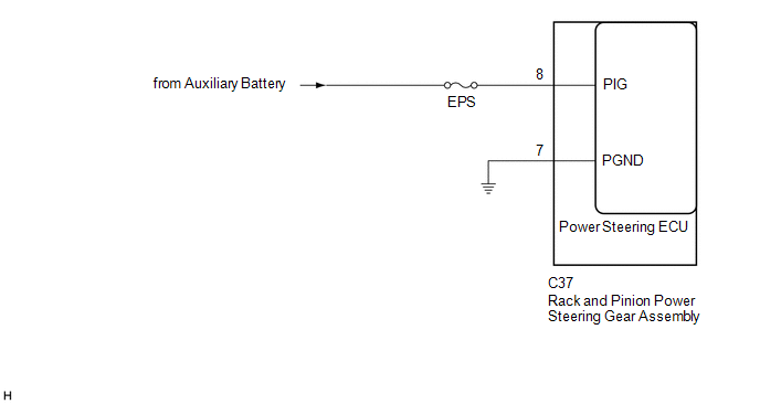
WIRING DIAGRAM
CAUTION / NOTICE / HINT
NOTICE:
-
If the rack and pinion power steering gear assembly has been replaced, perform assist map writing and torque sensor zero point calibration.
Click here
.gif)
- Inspect the fuses for circuits related to this system before performing the following procedure.
PROCEDURE
| 1. | CHECK HARNESS AND CONNECTOR (RACK AND PINION POWER STEERING GEAR ASSEMBLY - BODY GROUND) |
(a) Disconnect the C37 rack and pinion power steering gear assembly connector.

| *a | Front view of wire harness connector (to Rack and Pinion Power Steering Gear Assembly) | - | - |
(b) Measure the voltage according to the value(s) in the table below.
Standard Voltage:
| Tester Connection | Condition | Specified Condition |
|---|---|---|
| C37-8 (PIG) - Body ground | Always | 9 to 16 V |
(c) Measure the resistance according to the value(s) in the table below.
Standard Resistance:
| Tester Connection | Condition | Specified Condition |
|---|---|---|
| C37-7 (PGND) - Body ground | Always | Below 1 Ω |
| OK | .gif) | REPLACE RACK AND PINION POWER STEERING GEAR ASSEMBLY |
| NG | | REPAIR OR REPLACE HARNESS OR CONNECTOR |
READ NEXT:
 Error in Matching of ECUs (C1567)
DESCRIPTION The power steering ECU (rack and pinion power steering gear assembly) determines whether an incompatible hybrid vehicle control ECU or skid control ECU (brake booster with master cylinder
Assist Map Number Un-Writing (C1581)
DESCRIPTION This DTC will be stored if the power steering ECU (rack and pinion power steering gear assembly) determines that the assist map is not written in the ECU. DTC No. Detection Item DTC
Assist Map Number Mismatch (C1582)
DESCRIPTION When an incorrect hybrid vehicle control ECU or skid control ECU (brake booster with master cylinder assembly) is installed after the assist map has been written to the power steering ECU
SEE MORE:
Installation
INSTALLATION PROCEDURE 1. INSTALL TILT AND TELESCOPIC SWITCH (a) Engage the claw to install the tilt and telescopic switch. (b) Connect the tilt and telescopic connector to the tilt and telescopic switch. (c) Connect the spiral cable connector to the spiral cable sub-assembly. 2. CONNECT CABLE TO NE
Removal
REMOVAL CAUTION / NOTICE / HINT NOTICE: This procedure includes the removal of small-head bolts. Refer to Small-Head Bolts of Basic Repair Hint to identify the small-head bolts. Click here PROCEDURE 1. DISCONNECT NO. 1 VACUUM HOSE CONNECTOR (a) Pinch the retainer of the No. 1 vacuum hose connector
