Lexus ES: Parts Location
PARTS LOCATION
ILLUSTRATION
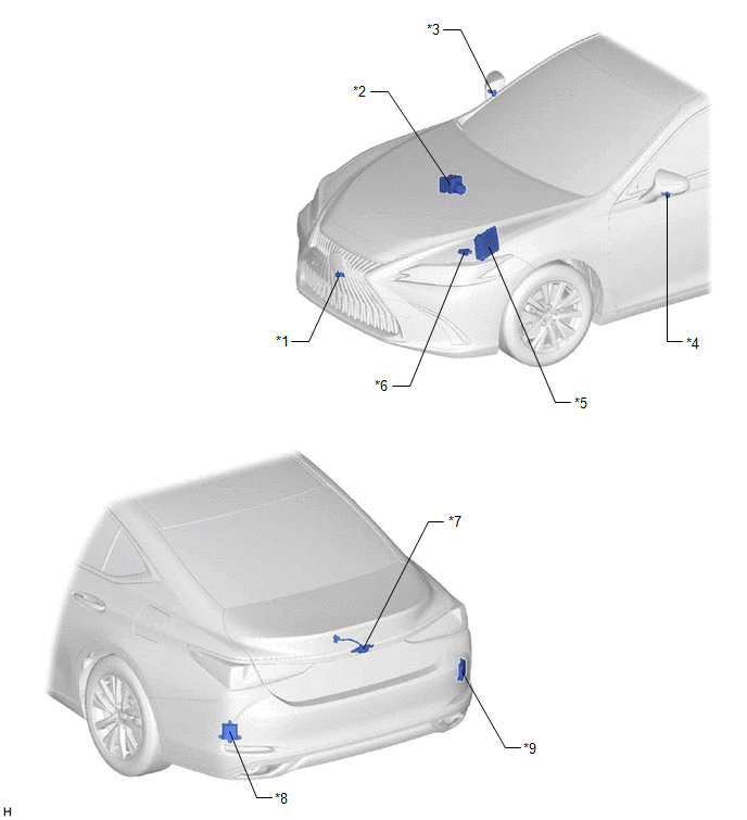
| *1 | FRONT TELEVISION CAMERA ASSEMBLY | *2 | BRAKE ACTUATOR ASSEMBLY - SKID CONTROL ECU |
| *3 | SIDE TELEVISION CAMERA ASSEMBLY RH | *4 | SIDE TELEVISION CAMERA ASSEMBLY LH |
| *5 | ECM | *6 | PARK/NEUTRAL POSITION SWITCH ASSEMBLY |
| *7 | REAR TELEVISION CAMERA ASSEMBLY | *8 | BLIND SPOT MONITOR SENSOR LH |
| *9 | BLIND SPOT MONITOR SENSOR RH | *10 | OUTER REAR VIEW MIRROR ASSEMBLY LH |
| *11 | OUTER REAR VIEW MIRROR ASSEMBLY RH | - | - |
ILLUSTRATION
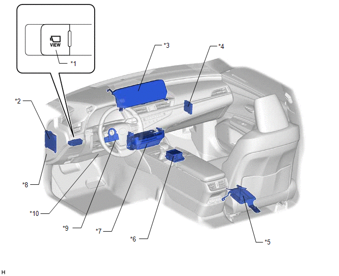
| *1 | PANORAMIC VIEW MONITOR SWITCH (NO. 2 COMBINATION SWITCH ASSEMBLY) | *2 | MAIN BODY ECU (MULTIPLEX NETWORK BODY ECU) |
| *3 | MULTI-DISPLAY ASSEMBLY | *4 | CLEARANCE WARNING ECU ASSEMBLY |
| *5 | PARKING ASSIST ECU | *6 | REMOTE TOUCH (REMOTE OPERATION CONTROLLER ASSEMBLY) |
| *7 | RADIO RECEIVER ASSEMBLY | *8 | INSTRUMENT PANEL JUNCTION BLOCK ASSEMBLY - ECU-IG1 NO. 3 FUSE - ECU-DCC NO. 1 FUSE - ECU-ACC FUSE - ECU-B NO. 2 FUSE - ECU-IG1 NO. 2 FUSE - BKUP LP Relay |
| *9 | STEERING SENSOR | *10 | DLC3 |
READ NEXT:
 Precaution
PRECAUTION PRECAUTION FOR DISCONNECTING CABLE FROM NEGATIVE BATTERY TERMINAL NOTICE: When disconnecting the cable from the negative (-) battery terminal, initialize the following systems after the cab
Problem Symptoms Table
PROBLEM SYMPTOMS TABLE NOTICE:
The following inspection procedure of the panoramic view monitor system is described on the assumption that the audio and visual system*1 or navigation system*2 is no
System Description
SYSTEM DESCRIPTION GENERAL (a) This system has front, passenger side, driver side and rear television camera assemblies mounted around the vehicle to display around the vehicle on the multi-display as
SEE MORE:
Power Window Motor Malfunction (B2311)
DESCRIPTION The power window regulator motor assemblies are operated by the multiplex network master switch assembly, power window regulator switch assembly or rear power window regulator switch assemblies. The power window regulator motor assemblies have motor, regulator and ECU functions. This DTC
On-vehicle Inspection
ON-VEHICLE INSPECTION PROCEDURE 1. CHECK AUXILIARY BATTERY (a) Check that the auxiliary battery cables are connected to the correct terminals. If they are not, connect them properly. (b) Check the auxiliary battery for damage and deformation. If severe damage, deformation or leakage is found, replac
