Lexus ES: Parts Location
PARTS LOCATION
ILLUSTRATION
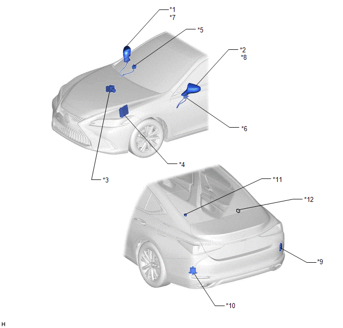
| *1 | OUTER REAR VIEW MIRROR ASSEMBLY RH | *2 | OUTER REAR VIEW MIRROR ASSEMBLY LH |
| *3 | BRAKE ACTUATOR ASSEMBLY - SKID CONTROL ECU | *4 | ECM |
| *5 | OUTER MIRROR CONTROL ECU ASSEMBLY RH | *6 | OUTER MIRROR CONTROL ECU ASSEMBLY LH |
| *7 | OUTER REAR VIEW MIRROR INDICATOR RH | *8 | OUTER REAR VIEW MIRROR INDICATOR LH |
| *9 | BLIND SPOT MONITOR SENSOR RH (MASTER) | *10 | BLIND SPOT MONITOR SENSOR LH (SLAVE) |
| *11 | RCTA BUZZER (BLIND SPOT MONITOR BUZZER) | *12 | No. 24 CAN JUNCTION CONNECTOR |
ILLUSTRATION
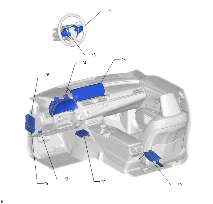
| *1 | STEERING PAD SWITCH ASSEMBLY | *2 | DLC3 |
| *3 | STEERING SENSOR | *4 | COMBINATION METER ASSEMBLY - MULTI-INFORMATION DISPLAY |
| *5 | INSTRUMENT PANEL JUNCTION BLOCK ASSEMBLY - ECU-IG1 NO. 4 FUSE - IG1-NO. 1 RELAY | *6 | MAIN BODY ECU (MULTIPLEX NETWORK BODY ECU) |
| *7 | AIRBAG SENSOR ASSEMBLY - YAW RATE AND ACCELERATION SENSOR | *8 | MULTI-DISPLAY ASSEMBLY |
| *9 | PARKING ASSIST ECU (w/ Panoramic View Monitor System) | - | - |
READ NEXT:
 Power Source Circuit
DESCRIPTION This circuit provides power to operate the blind spot monitor sensor. WIRING DIAGRAM CAUTION / NOTICE / HINT NOTICE: Inspect the fuses for circuits related to this system before performin
Precaution
PRECAUTION PRECAUTION FOR DISCONNECTING CABLE FROM NEGATIVE BATTERY TERMINAL NOTICE: When disconnecting the cable from the negative (-) battery terminal, initialize the following systems after the cab
Problem Symptoms Table
PROBLEM SYMPTOMS TABLE HINT:
Use the table below to help determine the cause of problem symptoms. If multiple suspected areas are listed, the potential causes of the symptoms are listed in order of
SEE MORE:
Kick Sensor Circuit (B2205)
DESCRIPTION DTC B2205 is output when the luggage closer motor assembly detects that the kick door control sensor is stuck on. DTC No. Detection Item DTC Detection Condition Trouble Area B2205 Kick Sensor Circuit One of the following conditions is met for approximately 60 seconds or
Precaution
PRECAUTION CAUTION:
Never perform work on fuel system components near any possible ignition sources.
Vaporized fuel could ignite, resulting in a serious accident.
Do not perform work on fuel system components without first disconnecting the cable from the negative (-) auxiliary battery termi
