Lexus ES: Power Source Circuit
DESCRIPTION
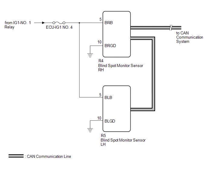
This circuit provides power to operate the blind spot monitor sensor.
WIRING DIAGRAM
CAUTION / NOTICE / HINT
NOTICE:
Inspect the fuses for circuits related to this system before performing the following procedure.
PROCEDURE
| 1. | CHECK HARNESS AND CONNECTOR (BLIND SPOT MONITOR SENSOR RH POWER SOURCE) |
(a) Disconnect the R4 blind spot monitor sensor RH connector.
(b) Measure the voltage according to the value(s) in the table below.
Standard Voltage:
| Tester Connection | Condition | Specified Condition |
|---|---|---|
| R4-5 (BRB) - Body ground | Engine switch on (IG) | 11 to 14 V*1 10.5 to 16 V*2 |
| R4-5 (BRB) - Body ground | Engine switch off | Below 1 V |
- *1: w/o Stop and Start System
- *2: w/ Stop and Start System
| NG | .gif) | REPAIR OR REPLACE HARNESS OR CONNECTOR |
|
.gif)
| 2. | CHECK HARNESS AND CONNECTOR (BLIND SPOT MONITOR SENSOR RH - BODY GROUND) |
(a) Measure the resistance according to the value(s) in the table below.
Standard Resistance:
| Tester Connection | Condition | Specified Condition |
|---|---|---|
| R4-10 (BRGD) - Body ground | Always | Below 1 Ω |
| NG | | REPAIR OR REPLACE HARNESS OR CONNECTOR |
|
| 3. | CHECK HARNESS AND CONNECTOR (BLIND SPOT MONITOR SENSOR LH POWER SOURCE) |
(a) Disconnect the R5 blind spot monitor sensor LH connector.
(b) Measure the voltage according to the value(s) in the table below.
Standard Voltage:
| Tester Connection | Condition | Specified Condition |
|---|---|---|
| R5-5 (BLB) - Body ground | Engine switch on (IG) | 11 to 14 V |
| R5-5 (BLB) - Body ground | Engine switch off | Below 1 V |
| NG | | REPAIR OR REPLACE HARNESS OR CONNECTOR |
|
| 4. | CHECK HARNESS AND CONNECTOR (BLIND SPOT MONITOR SENSOR LH - BODY GROUND) |
(a) Measure the resistance according to the value(s) in the table below.
Standard Resistance:
| Tester Connection | Condition | Specified Condition |
|---|---|---|
| R5-10 (BLGD) - Body ground | Always | Below 1 Ω |
| OK | | PROCEED TO NEXT SUSPECTED AREA SHOWN IN PROBLEM SYMPTOMS TABLE |
| NG | | REPAIR OR REPLACE HARNESS OR CONNECTOR |
READ NEXT:
 Precaution
PRECAUTION PRECAUTION FOR DISCONNECTING CABLE FROM NEGATIVE BATTERY TERMINAL NOTICE: When disconnecting the cable from the negative (-) battery terminal, initialize the following systems after the cab
Problem Symptoms Table
PROBLEM SYMPTOMS TABLE HINT:
Use the table below to help determine the cause of problem symptoms. If multiple suspected areas are listed, the potential causes of the symptoms are listed in order of
System Description
SYSTEM DESCRIPTION GENERAL (a) The blind spot monitor system has a blind spot monitor function. (1) Blind spot monitor function
The blind spot monitor function is a function that assists the driver
SEE MORE:
Control Module Communication Bus Off (U0073,U0100,U0126,U0129,U0140,U0163,U0233,U023B,U0265,U1110)
DESCRIPTION These DTCs are stored if there is a malfunction in the CAN communication system connected to the parking assist ECU. HINT: If CAN communication system DTCs are stored, they may also be stored in other systems. DTC No. Detection Item DTC Detection Condition Trouble Area U0073
Components
COMPONENTS ILLUSTRATION *1 BATTERY CLAMP SUB-ASSEMBLY - - N*m (kgf*cm, ft.*lbf): Specified torque - - ILLUSTRATION *1 TRANSMISSION CONTROL CABLE ASSEMBLY *2 TRANSMISSION CONTROL SHAFT LEVER *3 PARK/NEUTRAL POSITION SWITCH ASSEMBLY *4 WASHER Tighteni
