
Lexus ES: Parts Location
PARTS LOCATION
ILLUSTRATION
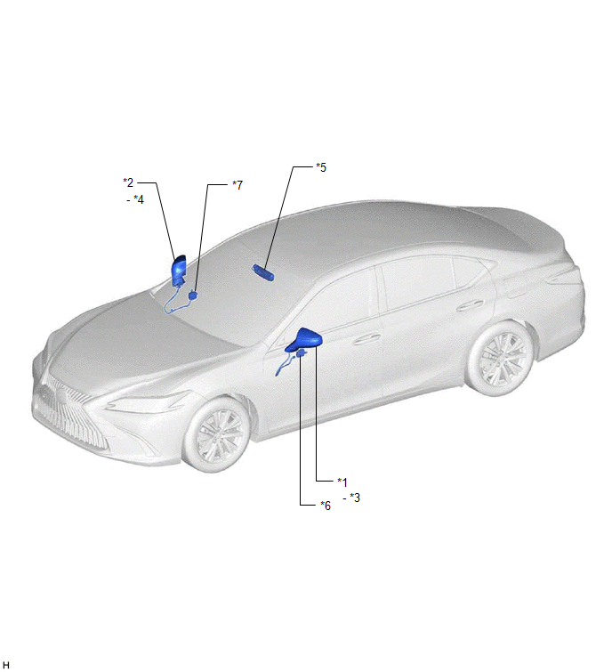
| *1 | OUTER REAR VIEW MIRROR ASSEMBLY (DRIVER DOOR) | *2 | OUTER REAR VIEW MIRROR ASSEMBLY (FRONT PASSENGER DOOR) |
| *3 | OUTER MIRROR (DRIVER DOOR) | *4 | OUTER MIRROR (FRONT PASSENGER DOOR) |
| *5 | INNER REAR VIEW MIRROR ASSEMBLY | *6 | OUTER MIRROR CONTROL ECU ASSEMBLY (DRIVER DOOR) |
| *7 | OUTER MIRROR CONTROL ECU ASSEMBLY (FRONT PASSENGER DOOR) | - | - |
ILLUSTRATION
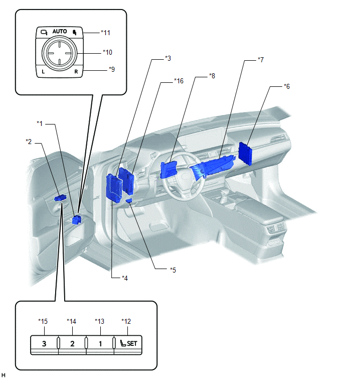
| *1 | OUTER MIRROR SWITCH ASSEMBLY | *2 | SEAT MEMORY SWITCH |
| *3 | MAIN BODY ECU (MULTIPLEX NETWORK BODY ECU) | *4 | INSTRUMENT PANEL JUNCTION BLOCK ASSEMBLY - DOOR F/R FUSE - DOOR F/L FUSE - ECU-IG1 NO. 4 FUSE - ECU-DCC NO. 2 FUSE |
| *5 | DLC3 | *6 | CERTIFICATION ECU (SMART KEY ECU ASSEMBLY) |
| *7 | REAR WINDOW DEFOGGER SWITCH (AIR CONDITIONING CONTROL ASSEMBLY) | *8 | AIR CONDITIONING AMPLIFIER ASSEMBLY |
| *9 | MIRROR SELECT SWITCH | *10 | MIRROR ADJUST SWITCH |
| *11 | RETRACTABLE OUTER MIRROR SWITCH | *12 | SET SWITCH |
| *13 | M1 SWITCH | *14 | M2 SWITCH |
| *15 | M3 SWITCH | *16 | HYBRID VEHICLE CONTROL ECU |
READ NEXT:
 System Diagram
SYSTEM DIAGRAM Communication Table Sender Receiver Signal Line Main Body ECU (Multiplex Network Body ECU) Outer Mirror Control ECU Assembly
IG signal
ACC signal
Outer mirror
System Description
SYSTEM DESCRIPTION POWER MIRROR CONTROL SYSTEM (w/ Memory) DESCRIPTION (a) This system has the following functions: electrical remote control mirror function, memory and reactivation function, power r
How To Proceed With Troubleshooting
CAUTION / NOTICE / HINT HINT:
Use the following procedure to troubleshoot the power mirror control system (w/ Memory).
*: Use the Techstream.
PROCEDURE 1. VEHICLE BROUGHT TO WORKSHOP
SEE MORE:
Remote Touch Screen Does not Generate Vibration Feedback
DESCRIPTION When each button displayed on the multi-display assembly is selected via remote touch screen operation, the remote touch screen generates vibration feedback according to communication between the remote touch and radio receiver assembly. CAUTION / NOTICE / HINT NOTICE:
Depending on th
Lost Communication With ECM/PCM "A" (U0100-U0122,U0124,U0126,U1103)
DESCRIPTION The absorber control ECU receives signals from the ECM, skid control ECU (brake actuator assembly), airbag ECU assembly, steering sensor and engine stop and start ECU* via CAN communication. When DTCs indicating a CAN communication system malfunction are output, repair the CAN communicat
