Lexus ES: System Diagram
SYSTEM DIAGRAM
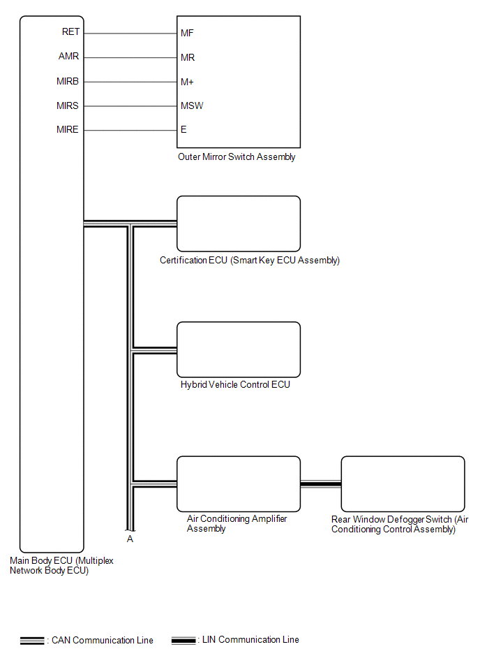
 Communication Table
 | Sender | Receiver | Signal | Line |
|---|---|---|---|
| Main Body ECU (Multiplex Network Body ECU) | Outer Mirror Control ECU Assembly |
| CAN |
| Outer Mirror Control ECU Assembly | Main Body ECU (Multiplex Network Body ECU) |
| CAN |
| Certification ECU (Smart Key ECU Assembly) | Main Body ECU (Multiplex Network Body ECU) | Key ID signal | CAN |
| Air Conditioning Amplifier Assembly | Outer Mirror Control ECU Assembly | Mirror heater drive request signal | CAN |
| Hybrid Vehicle Control ECU | Main Body ECU (Multiplex Network Body ECU) | Reverse signal | CAN |
| Rear Window Defogger switch (Air Conditioning Control Assembly) | Air Conditioning Amplifier Assembly | Mirror heater switch (rear window defogger switch) operation signal | LIN |
READ NEXT:
 System Description
SYSTEM DESCRIPTION POWER MIRROR CONTROL SYSTEM (w/ Memory) DESCRIPTION (a) This system has the following functions: electrical remote control mirror function, memory and reactivation function, power r
How To Proceed With Troubleshooting
CAUTION / NOTICE / HINT HINT:
Use the following procedure to troubleshoot the power mirror control system (w/ Memory).
*: Use the Techstream.
PROCEDURE 1. VEHICLE BROUGHT TO WORKSHOP
Operation Check
OPERATION CHECK CHECK ELECTRICAL REMOTE CONTROL MIRROR FUNCTION (a) Turn the power switch on (IG). (b) b. With the mirror select switch driver side switch on, check that the outer rear view mirror ass
SEE MORE:
Throttle/Pedal Position Sensor/Switch "B" Circuit Short to Ground (P022011)
DESCRIPTION Refer to DTC P012011. Click here DTC No. Detection Item DTC Detection Condition Trouble Area MIL Memory Note P022011 Throttle/Pedal Position Sensor/Switch "B" Circuit Short to Ground The output voltage of VTA2 is less than 2.05 V for 2 seconds or more (1 trip det
Components
COMPONENTS ILLUSTRATION *1 NO. 1 ENGINE UNDER COVER *2 NO. 2 ENGINE UNDER COVER ASSEMBLY *3 FRONT WHEEL OPENING EXTENSION PAD LH *4 FRONT WHEEL OPENING EXTENSION PAD RH *5 FRONT FENDER APRON SEAL LH - - N*m (kgf*cm, ft.*lbf): Specified torque - - ILLUSTRAT
© 2016-2026 Copyright www.lexguide.net
