Lexus ES: Parts Location
PARTS LOCATION
ILLUSTRATION
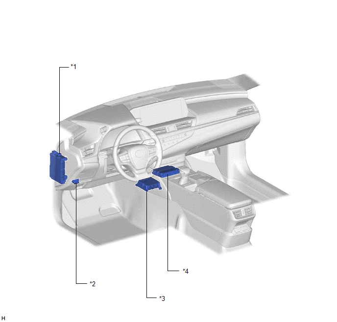
| *1 | INSTRUMENT PANEL JUNCTION BLOCK ASSEMBLY - DCM FUSE - ECU-IG2 NO. 3 FUSE | *2 | DLC3 |
| *3 | AIRBAG ECU ASSEMBLY | *4 | DCM (TELEMATICS TRANSCEIVER) - MOBILEPHONE BATTERY |
ILLUSTRATION
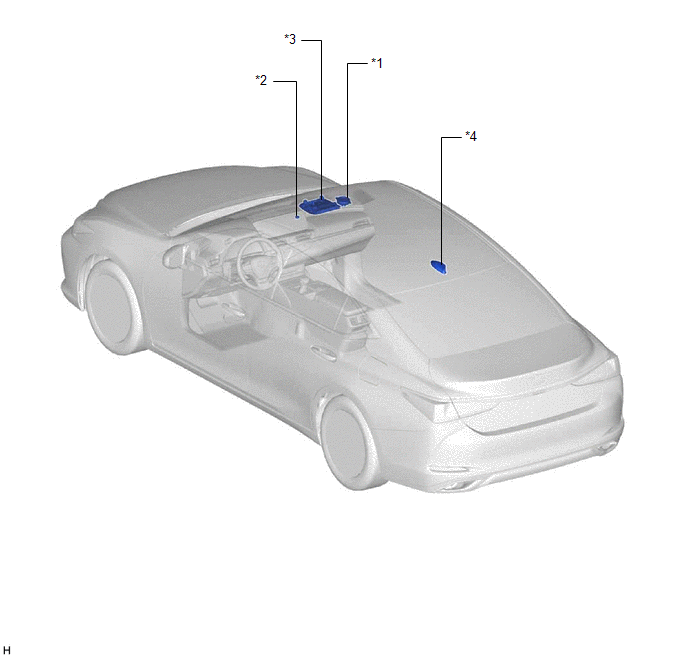
| *1 | FRONT NO. 2 SPEAKER ASSEMBLY (RH) | *2 | TELEPHONE MICROPHONE ASSEMBLY |
| *3 | MAP LIGHT SUB-ASSEMBLY - MANUAL (SOS) SWITCH | *4 | TELEPHONE AND GPS ANTENNA ASSEMBLY (for Roof Side) - Telephone Main - GPS |
ILLUSTRATION
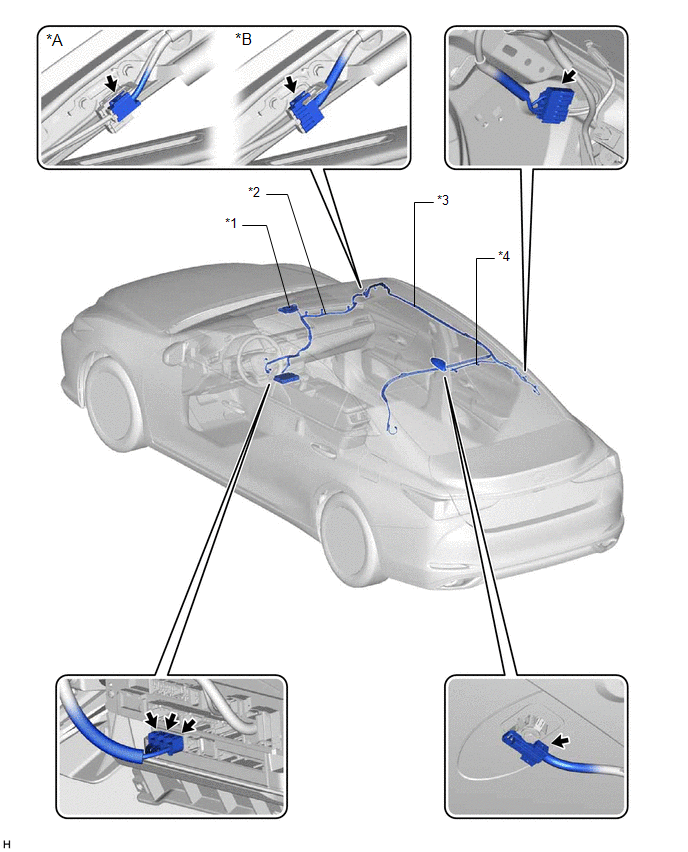
| *A | w/ SXM Function | *B | w/o SXM Function |
| *1 | TELEPHONE AND GPS ANTENNA ASSEMBLY (for Front Side) - Telephone Sub | *2 | TELEPHONE AND GPS ANTENNA CORD (ANTENNA CORD SUB-ASSEMBLY) |
| *3 | TELEPHONE AND GPS ANTENNA CORD (NO. 2 ANTENNA CORD SUB-ASSEMBLY) | *4 | TELEPHONE AND GPS ANTENNA CORD (NO. 3 ANTENNA CORD SUB-ASSEMBLY) |
READ NEXT:
 Precaution
PRECAUTION PRECAUTION FOR DISCONNECTING CABLE FROM NEGATIVE BATTERY TERMINAL NOTICE: When disconnecting the cable from the negative (-) battery terminal, initialize the following systems after the ter
Problem Symptoms Table
PROBLEM SYMPTOMS TABLE HINT:
Use the table below to help determine the cause of problem symptoms. If multiple suspected areas are listed, the potential causes of the symptoms are listed in order of
Red Indicator Remains On
DESCRIPTION This means that the DCM (telematics transceiver) has detected a malfunction in the safety connect system and stored a DTC or specific vehicle control history (RoB) Code. PROCEDURE 1.
SEE MORE:
Brake Hold Operated Indicator Light Circuit
DESCRIPTION The brake hold operated indicator light illuminates when the brake hold system is operating (vehicle stopped due to brake fluid pressure hold) and turns off when the brake hold system operation is finished (brake fluid pressure decreases). The brake hold system may not operate depending
System Description
SYSTEM DESCRIPTION LIN COMMUNICATION SYSTEM DESCRIPTION The LIN communication system is used for communication between the components in the tables below. If communication cannot be performed through LIN communication such as when there is an open or short in a communication line, the master control
© 2016-2026 Copyright www.lexguide.net
