Lexus ES: Parts Location
PARTS LOCATION
ILLUSTRATION
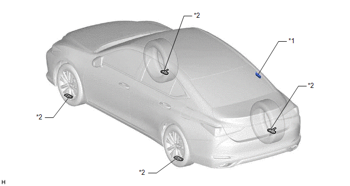
| *1 | TIRE PRESSURE WARNING ECU AND RECEIVER | *2 | TIRE PRESSURE WARNING VALVE AND TRANSMITTER |
ILLUSTRATION
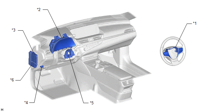
| *1 | STEERING PAD SWITCH ASSEMBLY | *2 | COMBINATION METER ASSEMBLY - TIRE PRESSURE WARNING LIGHT - MULTI-INFORMATION DISPLAY |
| *3 | MAIN BODY ECU (MULTIPLEX NETWORK BODY ECU) | *4 | DLC3 |
| *5 | SPIRAL CABLE SUB-ASSEMBLY | *6 | INSTRUMENT PANEL JUNCTION BLOCK ASSEMBLY - ECU-IG1 NO. 4 FUSE - ECU-B NO. 2 FUSE |
ILLUSTRATION
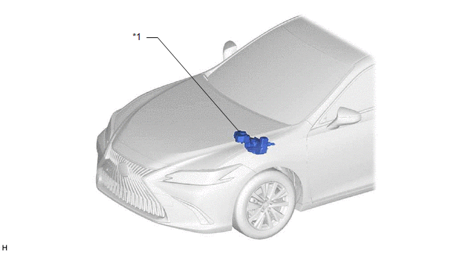
| *1 | SKID CONTROL ECU (BRAKE BOOSTER WITH MASTER CYLINDER ASSEMBLY) | - | - |
READ NEXT:
 System Diagram
SYSTEM DIAGRAM HINT: Each tire pressure warning valve and transmitter sends its transmitter ID, temperature and tire pressure information to the tire pressure warning ECU and receiver. Transmitti
How To Proceed With Troubleshooting
CAUTION / NOTICE / HINT HINT:
Use the following procedure to troubleshoot the tire pressure warning system.
Make sure that the wireless door lock control system has exited diagnostic mode before
Operation Check
OPERATION CHECK CHECK TIRE PRESSURE WARNING SYSTEM FUNCTION (a) Using the Data List, check that the current tire pressure is normal. Click here (1) Slowly reduce the tire pressure of the front or re
SEE MORE:
Installation
INSTALLATION PROCEDURE 1. INSTALL LOWER RADIATOR SUPPORT (a) Install the 2 lower radiator supports to the radiator assembly. 2. INSTALL RADIATOR SUPPORT CUSHION (a) Install the 2 radiator support cushions to the radiator assembly. 3. INSTALL RADIATOR ASSEMBLY (a) Engage the 2 guides. (b) Engage the
Installation
INSTALLATION CAUTION / NOTICE / HINT HINT:
Use the same procedure for the RH side and LH side.
The following procedure is for the LH side.
PROCEDURE 1. INSTALL FRONT DOOR OPENING TRIM WEATHERSTRIP (a) Align the alignment mark on the front door opening trim weatherstrip with the flange on the
© 2016-2026 Copyright www.lexguide.net
