Lexus ES: System Diagram
SYSTEM DIAGRAM
HINT:
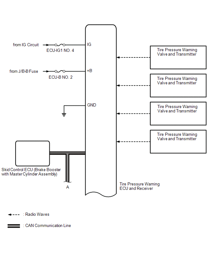
Each tire pressure warning valve and transmitter sends its transmitter ID, temperature and tire pressure information to the tire pressure warning ECU and receiver.
| Transmitting ECU (Transmitter) | Receiving ECU | Signal | Communication Method |
|---|---|---|---|
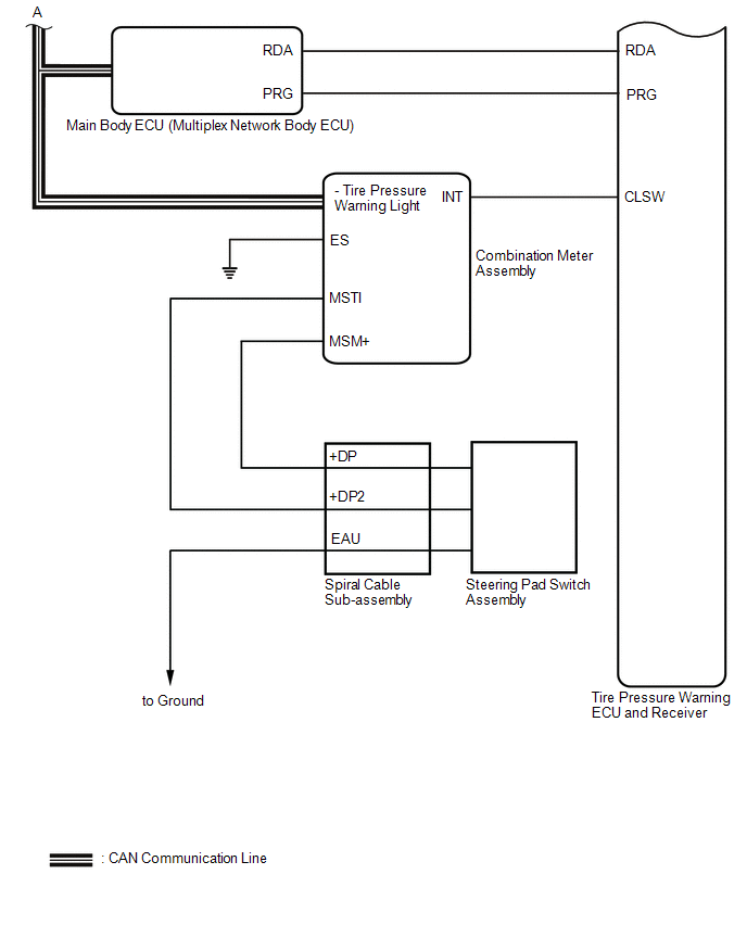
| Combination Meter Assembly | Main Body ECU (Multiplex Network Body ECU) | Vehicle speed signal | CAN communication line |
| Main Body ECU (Multiplex Network Body ECU) | Combination Meter Assembly | Tire pressure warning light signal | CAN communication line |
| Skid Control ECU (Brake Booster with Master Cylinder Assembly) | Tire Pressure Warning ECU and Receiver | Speed sensor signal | CAN communication line |
READ NEXT:
 How To Proceed With Troubleshooting
CAUTION / NOTICE / HINT HINT:
Use the following procedure to troubleshoot the tire pressure warning system.
Make sure that the wireless door lock control system has exited diagnostic mode before
Operation Check
OPERATION CHECK CHECK TIRE PRESSURE WARNING SYSTEM FUNCTION (a) Using the Data List, check that the current tire pressure is normal. Click here (1) Slowly reduce the tire pressure of the front or re
Registration
REGISTRATION PROCEDURE 1. BEFORE REGISTRATION NOTICE:
The transmitter ID is written on the tire pressure warning valve and transmitter. It is not possible to read the transmitter ID after installin
SEE MORE:
Dtc Check / Clear
DTC CHECK / CLEAR CHECK DTC (CHECK USING TECHSTREAM) (a) Connect the Techstream to the DLC3. (b) Turn the engine switch on (IG) and wait for 90 seconds. (c) Turn the Techstream on. (d) Enter the following menus: Body Electrical / Navigation System / Trouble Codes. Body Electrical > Navigation Sys
Problem Symptoms Table
PROBLEM SYMPTOMS TABLE NOTICE:
If the auxiliary battery voltage becomes low, auxiliary battery load control will operate in order to ensure sufficient power is supplied to the power steering system. In this case, the windshield deicer system may not operate.
HINT:
Use the table below to hel
© 2016-2026 Copyright www.lexguide.net
