Lexus ES: Parts Location
PARTS LOCATION
ILLUSTRATION
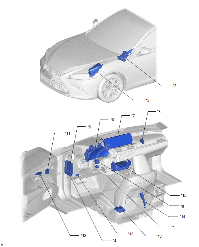
| *1 | TILT AND TELESCOPIC SWITCH | *2 | STEERING COLUMN ASSEMBLY - TILT MOTOR - TELESCOPIC MOTOR |
| *3 | NO. 1 ENGINE ROOM RELAY BLOCK AND NO. 1 JUNCTION BLOCK ASSEMBLY - TI&TE FUSE | *4 | INSTRUMENT PANEL JUNCTION BLOCK ASSEMBLY - ECU-DCC NO. 2 FUSE - ECU-IG1 NO. 4 FUSE |
| *5 | MAIN BODY ECU (MULTIPLEX NETWORK BODY ECU) | *6 | COMBINATION METER ASSEMBLY |
| *7 | MULTI-DISPLAY ASSEMBLY | *8 | NETWORK GATEWAY ECU |
| *9 | MULTIPLEX TILT AND TELESCOPIC ECU | *10 | DLC3 |
| *11 | OUTER MIRROR CONTROL ECU ASSEMBLY (Driver Door) | *12 | SEAT MEMORY SWITCH |
| *13 | POSITION CONTROL ECU ASSEMBLY (Driver Seat) | *14 | FRONT SEAT INNER BELT ASSEMBLY (Driver Seat) |
| *15 | RADIO RECEIVER ASSEMBLY | - | - |
READ NEXT:
 System Diagram
SYSTEM DIAGRAM Communication Table Transmitting ECU (Transmitter) Receiving ECU Signal Communication Method Main Body ECU (Multiplex Network Body ECU) Multiplex Tilt and Telescopic EC
System Description
SYSTEM DESCRIPTION FUNCTION OF MAIN COMPONENTS Component Function Multiplex tilt and telescopic ECU This ECU sends a control signal to the tilt motor (steering column assembly) and telescop
How To Proceed With Troubleshooting
CAUTION / NOTICE / HINT HINT: *: Use the Techstream. PROCEDURE 1. VEHICLE BROUGHT TO WORKSHOP
NEXT 2. INSPECT AUXILIARY BATTERY VOLTAGE (a) Measure the auxiliary bat
SEE MORE:
Camshaft Position "A" Actuator Bank 1 General Electrical Failure (P001001)
DESCRIPTION The VVT-iE system adjusts the intake valve timing using a motor. Compared to conventional hydraulic VVT systems, the valve timing can be adjusted within a wider range and can be retarded more when starting the engine. As the VVT-iE system can operate at low engine speeds and when the eng
Removal
REMOVAL CAUTION / NOTICE / HINT The necessary procedures (adjustment, calibration, initialization or registration) that must be performed after parts are removed and installed, or replaced during ECM removal/installation are shown below. Necessary Procedures After Parts Removed/Installed/Replaced
© 2016-2026 Copyright www.lexguide.net
