Lexus ES: System Diagram
SYSTEM DIAGRAM
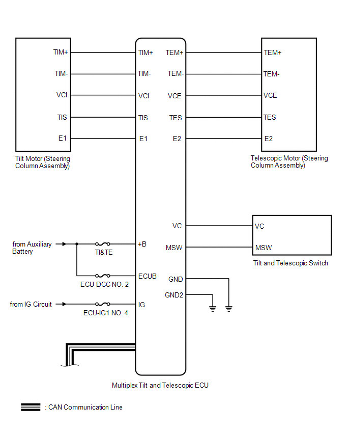
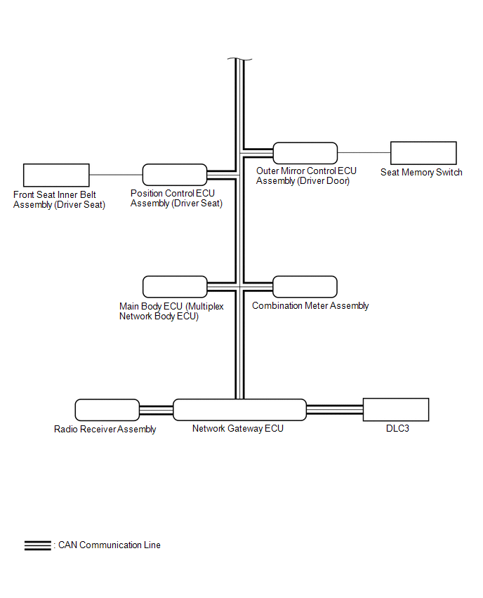 Communication Table
 | Transmitting ECU (Transmitter) | Receiving ECU | Signal | Communication Method |
|---|---|---|---|
| Main Body ECU (Multiplex Network Body ECU) | Multiplex Tilt and Telescopic ECU |
| CAN |
| Position Control ECU Assembly (Driver Seat) | Multiplex Tilt and Telescopic ECU |
| |
| Combination Meter Assembly | Multiplex Tilt and Telescopic ECU | Vehicle speed signal | |
| Multiplex Tilt and Telescopic ECU | Main Body ECU (Multiplex Network Body ECU) | State signal of tilt and telescopic steering | |
| Multiplex Tilt and Telescopic ECU | Position Control ECU Assembly (Driver Seat) |
| |
| Tilt and Telescopic Switch | Multiplex Tilt and Telescopic ECU | Tilt and Telescopic Switch signal | Direct line |
READ NEXT:
 System Description
SYSTEM DESCRIPTION FUNCTION OF MAIN COMPONENTS Component Function Multiplex tilt and telescopic ECU This ECU sends a control signal to the tilt motor (steering column assembly) and telescop
How To Proceed With Troubleshooting
CAUTION / NOTICE / HINT HINT: *: Use the Techstream. PROCEDURE 1. VEHICLE BROUGHT TO WORKSHOP
NEXT 2. INSPECT AUXILIARY BATTERY VOLTAGE (a) Measure the auxiliary bat
Customize Parameters
CUSTOMIZE PARAMETERS CUSTOMIZE POWER TILT AND POWER TELESCOPIC STEERING COLUMN SYSTEM HINT: The following items can be customized. NOTICE:
When the customer requests a change in a function, first m
SEE MORE:
CAN Communication Failure (Message Registry) (U1000)
DESCRIPTION The headlight ECU sub-assembly LH or headlight ECU sub-assembly RH stores this DTC if it detects an internal malfunction related to the CAN communication system. for LED Type Turn Signal Light DTC No. Detection Item DTC Detection Condition Trouble Area DTC Output from U100
Installation
INSTALLATION CAUTION / NOTICE / HINT NOTICE: This procedure includes the installation of small-head bolts. Refer to Small-Head Bolts of Basic Repair Hint to identify the small-head bolts. Click here PROCEDURE 1. INSTALL CAMSHAFT HINT: Perform inspection after repair after replacing the camshaft, N
© 2016-2026 Copyright www.lexguide.net
