Lexus ES: Parts Location
Lexus ES (XZ10) Service Manual / Steering / Power Assist Systems / Power Steering System (for Hv Model) / Parts Location
PARTS LOCATION
ILLUSTRATION
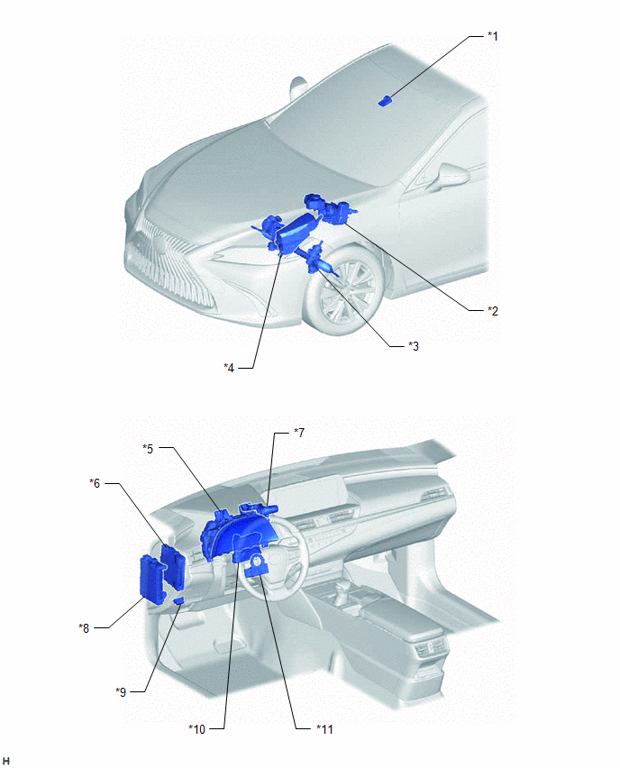
| *1 | FORWARD RECOGNITION CAMERA | *2 | BRAKE BOOSTER WITH MASTER CYLINDER ASSEMBLY - SKID CONTROL ECU |
| *3 | RACK AND PINION POWER STEERING GEAR ASSEMBLY - POWER STEERING ECU -POWER STEERING MOTOR -TORQUE SENSOR | *4 | NO. 1 ENGINE ROOM RELAY BLOCK AND NO. 1 JUNCTION BLOCK ASSEMBLY - EPS FUSE |
| *5 | COMBINATION METER ASSEMBLY | *6 | HYBRID VEHICLE CONTROL ECU |
| *7 | DRIVE MODE SELECT SWITCH (COMBINATION SWITCH ASSEMBLY) | *8 | INSTRUMENT PANEL JUNCTION BLOCK ASSEMBLY - IG1-NO. 1 RELAY - EPS-IG1 FUSE |
| *9 | DLC3 | *10 | AIR CONDITIONING AMPLIFIER ASSEMBLY |
| *11 | STEERING SENSOR | - | - |
READ NEXT:
 System Diagram
SYSTEM DIAGRAM
System Description
SYSTEM DESCRIPTION DESCRIPTION (a) The power steering ECU (rack and pinion power steering gear assembly) generates the necessary steering assist torque by calculating the steering assist force and con
How To Proceed With Troubleshooting
CAUTION / NOTICE / HINT HINT:
Use the following procedure to troubleshoot the power steering system.
*: Use the Techstream.
PROCEDURE 1. VEHICLE BROUGHT TO WORKSHOP
NEXT
SEE MORE:
Lost Communication with Brake System Control Module (U0129)
DESCRIPTION The tire pressure warning ECU and receiver receives signals from the skid control ECU (brake booster with master cylinder assembly) via CAN communication system. DTC No. Detection Item DTC Detection Condition Trouble Area Note U0129 Lost Communication with Brake System C
Hybrid/EV Battery Cooling Fan 1 Control Circuit High (P0A8100,P0A8115)
DESCRIPTION Refer to the description for DTC P0A8111. Click here DTC No. Detection Item DTC Detection Condition Trouble Area MIL Warning Indicate P0A8100 Hybrid/EV Battery Cooling Fan 1 Control Circuit High Both of the following conditions are met:
The HV battery temperatur
© 2016-2026 Copyright www.lexguide.net
