Lexus ES: Parts Location
PARTS LOCATION
ILLUSTRATION
.png)
| *1 | ACCELERATOR PEDAL SENSOR ASSEMBLY | *2 | COMBINATION METER ASSEMBLY |
| *3 | AIR CONDITIONING AMPLIFIER ASSEMBLY | *4 | SHIFT PADDLE SWITCH (TRANSMISSION SHIFT SWITCH ASSEMBLY) |
| *5 | NO. 3 RELAY BLOCK - IGCT RELAY | *6 | SHIFT POSITION INDICATOR |
| *7 | DRIVE MODE SELECT SWITCH (COMBINATION SWITCH ASSEMBLY) | *8 | SHIFT LOCK CONTROL UNIT ASSEMBLY - TRANSMISSION CONTROL SWITCH |
| *9 | AIRBAG ECU ASSEMBLY | *10 | HYBRID VEHICLE CONTROL ECU |
| *11 | NO. 4 RELAY BLOCK - PCU FUSE - IGCT NO. 2 FUSE - PM-IGCT FUSE - BATT FAN FUSE - INV W/PMP FUSE | *12 | INSTRUMENT PANEL JUNCTION BLOCK ASSEMBLY - ECU-B NO. 2 FUSE - BKUP LP FUSE - ECU-IG1 NO. 1 FUSE - ECU-ACC FUSE - ECU-IG1 NO. 3 FUSE |
| *13 | SPIRAL CABLE WITH SENSOR SUB-ASSEMBLY | *14 | DLC3 |
| *15 | EV MODE SWITCH (NO. 3 COMBINATION SWITCH ASSEMBLY) | - | - |
ILLUSTRATION
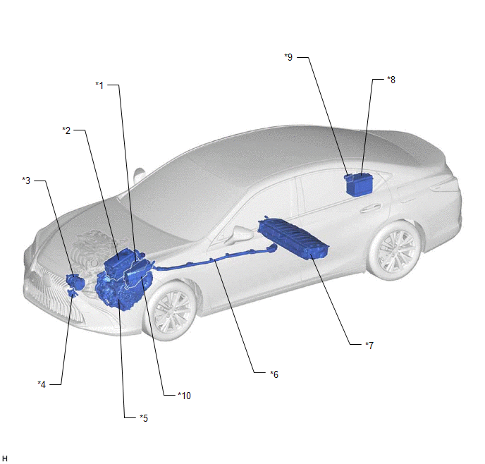
| *1 | ECM | *2 | INVERTER WITH CONVERTER ASSEMBLY |
| *3 | COMPRESSOR WITH MOTOR ASSEMBLY | *4 | INVERTER WATER PUMP ASSEMBLY |
| *5 | HYBRID VEHICLE TRANSAXLE ASSEMBLY | *6 | HV FLOOR UNDER WIRE |
| *7 | HV BATTERY | *8 | AUXILIARY BATTERY |
| *9 | FUSIBLE LINK BLOCK ASSEMBLY - IGCT FUSE | *10 | NO. 1 ENGINE ROOM RELAY BLOCK AND NO. 1 JUNCTION BLOCK ASSEMBLY - ECU-IG2 NO. 1 FUSE - IG2 NO. 1 RELAY - DC/DC FUSE - IG2-MAIN FUSE |
ILLUSTRATION
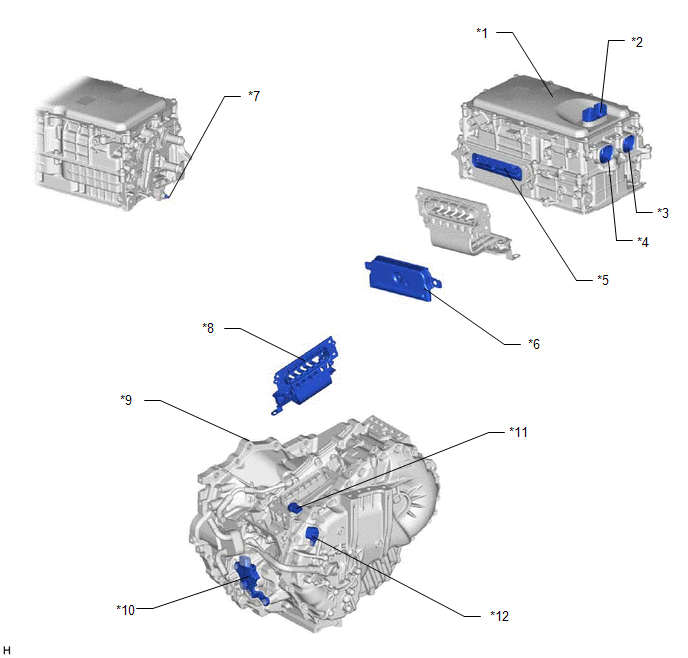
| *1 | INVERTER WITH CONVERTER ASSEMBLY | *2 | LOW VOLTAGE CONNECTOR |
| *3 | AIR CONDITIONING WIRE CONNECTION | *4 | HV FLOOR UNDER WIRE CONNECTION |
| *5 | MOTOR CABLE CONNECTION | *6 | INVERTER COVER - INTERLOCK |
| *7 | AMD TERMINAL | *8 | MOTOR CABLE |
| *9 | HYBRID VEHICLE TRANSAXLE ASSEMBLY | *10 | SHIFT LEVER POSITION SENSOR |
| *11 | MOTOR TEMPERATURE SENSOR AND GENERATOR TEMPERATURE SENSOR CONNECTOR | *12 | MOTOR RESOLVER, GENERATOR RESOLVER AND TRANSMISSION FLUID TEMPERATURE SENSOR CONNECTOR |
ILLUSTRATION
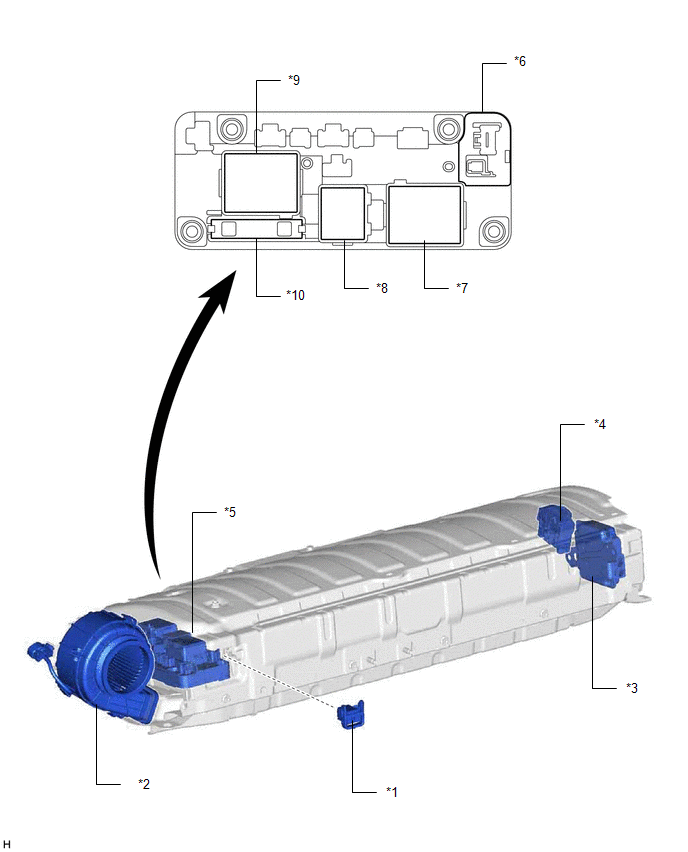
| *1 | SERVICE PLUG GRIP | *2 | BATTERY COOLING BLOWER ASSEMBLY |
| *3 | BATTERY VOLTAGE SENSOR | *4 | HYBRID BATTERY TERMINAL BLOCK |
| *5 | HV BATTERY JUNCTION BLOCK ASSEMBLY | *6 | BATTERY CURRENT SENSOR |
| *7 | SMRB | *8 | SMRP |
| *9 | SMRG | *10 | SYSTEM MAIN RESISTOR |
READ NEXT:
 System Diagram
SYSTEM DIAGRAM
How To Proceed With Troubleshooting
CAUTION / NOTICE / HINT HINT:
*: Use the Techstream
Use the following procedure to troubleshoot the hybrid control system.
PROCEDURE 1. VEHICLE BROUGHT TO WORKSHOP
NEXT
Utility
UTILITY ALL READINESS HINT:
With "All Readiness", you can check whether or not the DTC judgment has been completed by using the Techstream.
You should check "All Readiness" after simulating malfu
SEE MORE:
Lost Communication with Wiper System LIN BUS (B1373)
DESCRIPTION The main body ECU (multiplex network body ECU) and windshield wiper motor assembly communicate via LIN communication. The main body ECU (multiplex network body ECU) stores this DTC if communication becomes abnormal. DTC No. Detection Item DTC Detection Condition Trouble Area M
Parts Location
PARTS LOCATION ILLUSTRATION *1 OUTER REAR VIEW MIRROR ASSEMBLY (DRIVER DOOR) *2 OUTER REAR VIEW MIRROR ASSEMBLY (FRONT PASSENGER DOOR) *3 OUTER MIRROR (DRIVER DOOR) *4 OUTER MIRROR (FRONT PASSENGER DOOR) *5 INNER REAR VIEW MIRROR ASSEMBLY *6 OUTER MIRROR CONTROL ECU ASS
