Lexus ES: Parts Location
Lexus ES (XZ10) Service Manual / Engine & Hybrid System / Cruise Control / Lane Control System (for Hv Model) / Parts Location
PARTS LOCATION
ILLUSTRATION
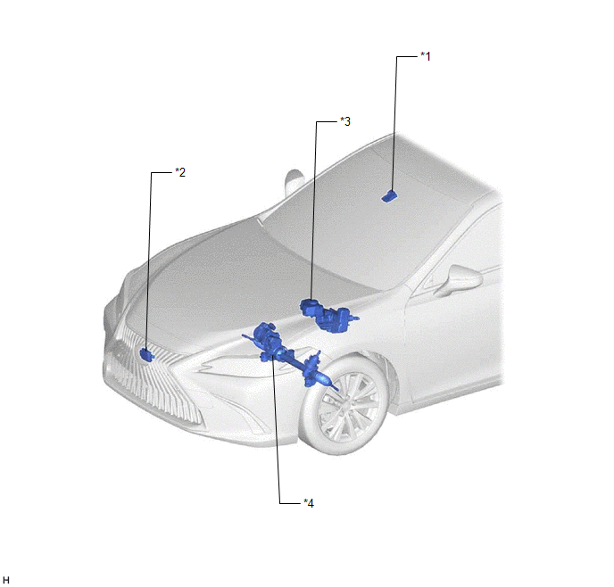
| *1 | FORWARD RECOGNITION CAMERA | *2 | MILLIMETER WAVE RADAR SENSOR ASSEMBLY |
| *3 | BRAKE BOOSTER WITH MASTER CYLINDER ASSEMBLY - SKID CONTROL ECU | *4 | RACK AND PINION POWER STEERING GEAR ASSEMBLY - POWER STEERING ECU |
ILLUSTRATION
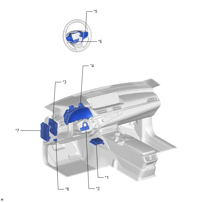
| *1 | AIRBAG ECU ASSEMBLY - YAW RATE SENSOR | *2 | STEERING SENSOR |
| *3 | HYBRID VEHICLE CONTROL ECU | *4 | COMBINATION METER ASSEMBLY - MULTI-INFORMATION DISPLAY - LTA INDICATOR - LTA BUZZER |
| *5 | STEERING PAD SWITCH ASSEMBLY - LTA MAIN SWITCH - FUNCTION SWITCH (CUSTOMIZE SWITCH) | *6 | STEERING VIBRATION ECU |
| *7 | INSTRUMENT PANEL JUNCTION BLOCK ASSEMBLY - ECU-IG1 NO. 3 FUSE | *8 | DLC3 |
READ NEXT:
 System Diagram
SYSTEM DIAGRAM
How To Proceed With Troubleshooting
CAUTION / NOTICE / HINT HINT:
Use the following procedure to troubleshoot the lane control system.
*: Use the Techstream.
PROCEDURE 1. VEHICLE BROUGHT TO WORKSHOP
NEXT
Customize Parameters
CUSTOMIZE PARAMETERS CUSTOMIZE LTA NOTICE:
When the customer requests a change in a function, first make sure that the function can be customized.
Be sure to make a note of the current settings b
SEE MORE:
Initialization
INITIALIZATION RESET BACK-UP BATTERY CONDITION HINT: If the back-up battery (mobilephone battery) has been replaced, it is necessary to perform the Reset Backup Battery Condition procedure. (a) Connect the Techstream to the DLC3. (b) Turn the power switch on (IG). (c) Turn the Techstream on. (d) Cho
System Description
SYSTEM DESCRIPTION GENERAL The windshield deicer system uses thin heater wires attached to the inside of the windshield glass to help deice the window surface more quickly. An indicator light illuminates while the system is operating. This system automatically turns off after approximately 15 minute
© 2016-2026 Copyright www.lexguide.net
