Lexus ES: System Diagram
Lexus ES (XZ10) Service Manual / Engine & Hybrid System / Cruise Control / Lane Control System (for Hv Model) / System Diagram
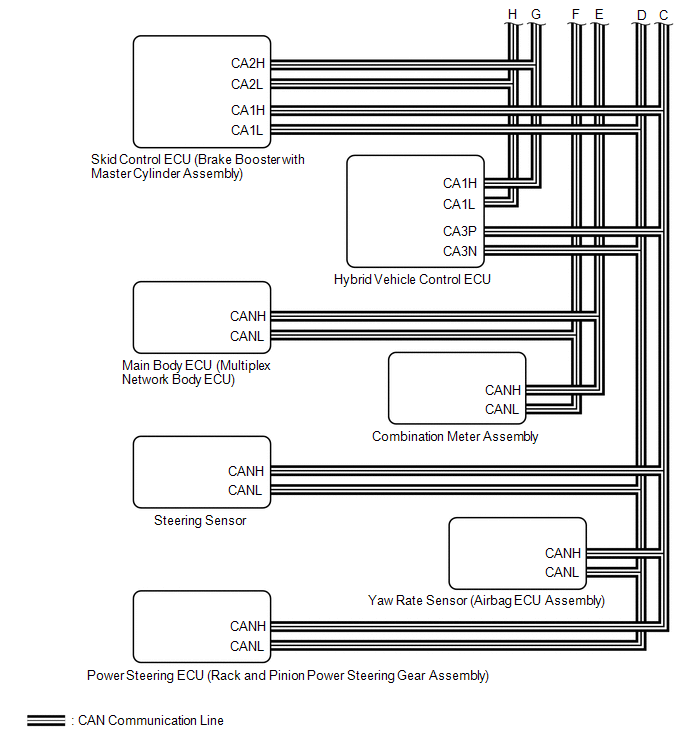
SYSTEM DIAGRAM
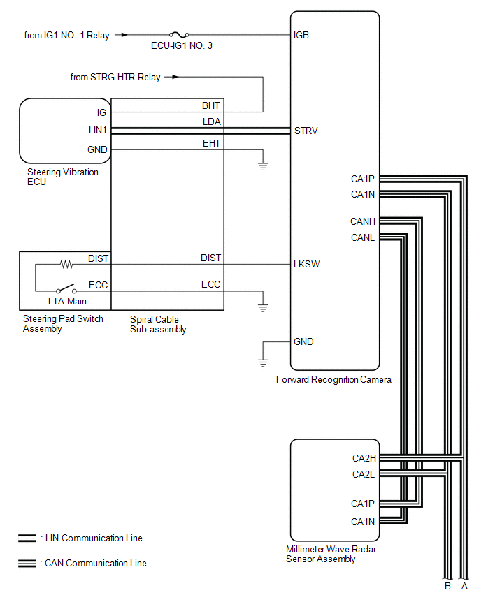
.png)
READ NEXT:
 How To Proceed With Troubleshooting
CAUTION / NOTICE / HINT HINT:
Use the following procedure to troubleshoot the lane control system.
*: Use the Techstream.
PROCEDURE 1. VEHICLE BROUGHT TO WORKSHOP
NEXT
Customize Parameters
CUSTOMIZE PARAMETERS CUSTOMIZE LTA NOTICE:
When the customer requests a change in a function, first make sure that the function can be customized.
Be sure to make a note of the current settings b
Problem Symptoms Table
PROBLEM SYMPTOMS TABLE HINT:
If CAN communication system and lane control system DTCs are not output and any of the following problem symptoms exist, perform troubleshooting by checking the appropr
SEE MORE:
Dtc Check / Clear
DTC CHECK / CLEAR CHECK DTC (CHECK USING TECHSTREAM) (a) Connect the Techstream to the DLC3. (b) Turn the power switch on (IG) and wait for 90 seconds. (c) Turn the Techstream on. (d) Enter the following menus: Body Electrical / Navigation System / Trouble Codes. Body Electrical > Navigation Syst
Parts Location
PARTS LOCATION ILLUSTRATION *1 DEF RELAY *2 REAR WINDOW DEFOGGER WIRE *3 NO. 1 ENGINE ROOM RELAY BLOCK AND NO. 1 JUNCTION BLOCK ASSEMBLY - DEF FUSE *4 BACK WINDOW GLASS ILLUSTRATION *1 REAR WINDOW DEFOGGER SWITCH (AIR CONDITIONING CONTROL ASSEMBLY) *2 DLC3 *3 A
© 2016-2026 Copyright www.lexguide.net
