Lexus ES: Parts Location
Lexus ES (XZ10) Service Manual / Engine & Hybrid System / A25a-fks (engine Control) / Ignition System / Parts Location
PARTS LOCATION
ILLUSTRATION
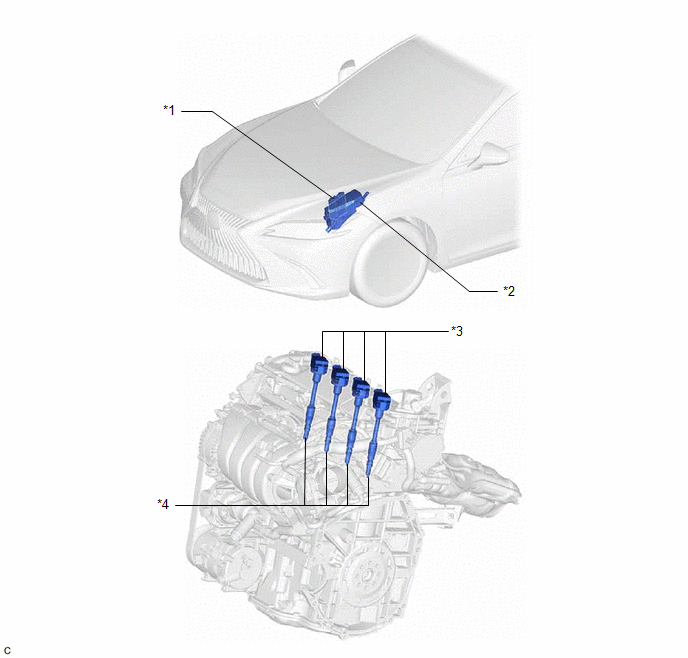
| *1 | ECM | *2 | NO. 1 ENGINE ROOM RELAY BLOCK AND NO. 1 JUNCTION BLOCK ASSEMBLY - INJ FUSE |
| *3 | IGNITION COIL ASSEMBLY | *4 | SPARK PLUG |
READ NEXT:
 System Diagram
SYSTEM DIAGRAM
On-vehicle Inspection
ON-VEHICLE INSPECTION CAUTION / NOTICE / HINT CAUTION: To prevent injury due to contact with an operating V-ribbed belt or cooling fan, keep your hands and clothing away from the V-ribbed belt and coo
Knock Sensor
ComponentsCOMPONENTS ILLUSTRATION *1 KNOCK CONTROL SENSOR - - N*m (kgf*cm, ft.*lbf): Specified torque - - InspectionINSPECTION PROCEDURE 1. INSPECT KNOCK CONTROL SENSOR (a
SEE MORE:
Diagnosis System
DIAGNOSIS SYSTEM DESCRIPTION (a) Parking support brake system data and Diagnostic Trouble Codes (DTCs) can be read from the Data Link Connector 3 (DLC3) of the vehicle. When the system seems to be malfunctioning, use the Techstream to check for malfunctions and to repair them. CHECK DLC3 (a) Check t
Components
COMPONENTS
ILLUSTRATION
*1
RESERVE TANK CAP
*2
DRAIN COCK PLUG
*3
NO. 1 ENGINE UNDER COVER
-
-
© 2016-2026 Copyright www.lexguide.net
