Lexus ES: Parts Location
PARTS LOCATION
ILLUSTRATION
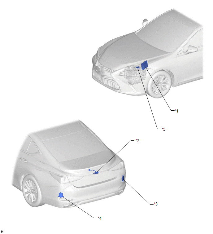
| *1 | ECM | *2 | REAR TELEVISION CAMERA ASSEMBLY |
| *3 | BLIND SPOT MONITOR SENSOR RH (w/ Blind Spot Monitor System) | *4 | BLIND SPOT MONITOR SENSOR LH (w/ Blind Spot Monitor System) |
| *5 | PARK/NEUTRAL POSITION SWITCH ASSEMBLY (for 8 inch display) | - | - |
ILLUSTRATION

| *1 | MAIN BODY ECU (MULTIPLEX NETWORK BODY ECU) | *2 | STEERING SENSOR |
| *3 | MULTI-DISPLAY ASSEMBLY | *4 | DLC3 |
| *5 | INSTRUMENT PANEL JUNCTION BLOCK ASSEMBLY - ECU-IG1 NO. 2 FUSE - ECU-DCC NO. 1 FUSE - IG1-NO. 1 RELAY - BKUP LP RELAY (for 8 inch display) | *6 | CLEARANCE WARNING ECU ASSEMBLY (w/ Parking Support Alert System) |
| *7 | RADIO RECEIVER ASSEMBLY | - | - |
READ NEXT:
 Precaution
PRECAUTION PRECAUTION FOR DISCONNECTING CABLE FROM NEGATIVE BATTERY TERMINAL NOTICE: When disconnecting the cable from the negative (-) battery terminal, initialize the following systems after the cab
Problem Symptoms Table
PROBLEM SYMPTOMS TABLE NOTICE:
The following inspection procedures for the parking assist monitor system are based on the assumption that the audio and visual system*1 or navigation system*2 is nor
Reverse Signal Circuit
DESCRIPTION The multi-display receives a reverse signal from the BK UP LP relay*1 or clearance warning ECU assembly*2.
*1: w/o Parking Support Alert System
*2: w/ Parking Support Alert System
SEE MORE:
Manifold Absolute Pressure / Barometric Pressure Sensor Circuit Short to Battery or Open (P010515)
DESCRIPTION Refer to DTC P010511. Click here DTC No. Detection Item DTC Detection Condition Trouble Area MIL Memory Note P010515 Manifold Absolute Pressure / Barometric Pressure Sensor Circuit Short to Battery or Open The manifold absolute pressure sensor output voltage is h
Removal
REMOVAL CAUTION / NOTICE / HINT The necessary procedures (adjustment, calibration, initialization or registration) that must be performed after parts are removed and installed, or replaced during rear door opening trim weatherstrip removal/installation are shown below. Necessary Procedure After Part
© 2016-2026 Copyright www.lexguide.net
